Bd h e – Craftsman 486.243223 User Manual
Page 5
5
B
D
F
F
F
C
D
D
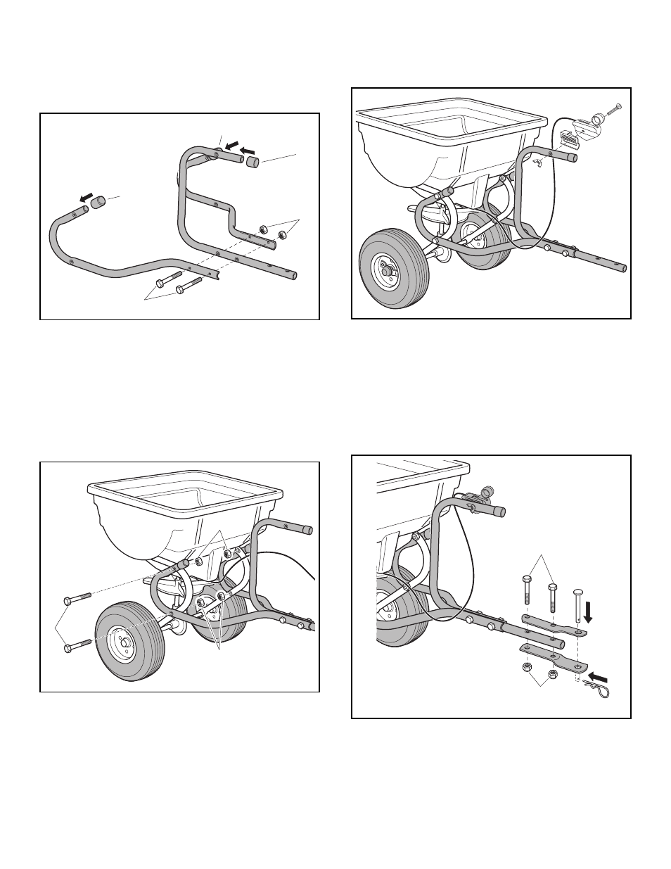
FIGURE 5
FIGURE 6
FIGURE 7
• Attach the (RH) and (LH) hitch tubes to the frame tube
using four 1/4" x 2" hexbolts (C) and 1/4" nylock nuts
(D).
Tighten. See figure 6.
• Assemble the Control Cable to the Hitch Control Tube
using the carriage bolt and nylon wing nut.
Tighten.
See figure 7.
• Assemble the (RH) and (LH) hitch tubes to the control
tube using two 1/4" x 1-3/4" hex bolts (B) and 1/4"
nylock nuts (D).
Tighten. See figure 5.
• Assemble the plastic caps onto the ends of the hitch
tubes and control tube as shown in figure 5.
FIGURE 8
B
D
H
E
• Assemble the Hitch Brackets to the Hitch Control Tube
using two 1/4" x 1-3/4" hex bolts (B) and 1/4" nuts (D).
Tighten. See figure 8.
• Assemble the hitch pin (H) through the hitch brackets
and secure with the 1/8" hair cotter pin (E). See figure
8.