Flexible capillary model, Wiring, Replacement of similar device by the l4017 – Honeywell L4017 User Manual
Page 4: Caution
Attention! The text in this document has been recognized automatically. To view the original document, you can use the "Original mode".
5. Insert the element into the element opening and
slip the asbestos washer over the capillary (Fig. 4).
With the 2 screws provided, securely fasten the control
to the furnace casing.
6. Position the element as described in Location
above, bending as necessary. Avoid sharp bends or
repeated flexing with the self-supporting model (Fig. 2).
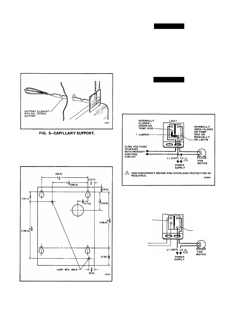
FLEXIBLE CAPILLARY MODEL
The element must be firmly held in position by use
of capillary support. Part No. 107324A, or similar
support (Fig. 5).
WIRING
REPLACEMENT OF SIMILAR DEVICE BY THE
L4017
Adapter plate bag assembly. Part No. 21136E, is
available to fit mounting holes of similar controls
(Fig. 6).
CAUTION
Disconnect power supply before connecting wiring
to prevent electrical shock or equipment damage.
All wiring must comply with applicable local codes
and ordinances. Follow the system wiring diagrams
furnished with the burner. Figs. 7 and 8 illustrate the
connections to the L4017. For ease in wiring, 2 conduit
knockouts are furnished at the bottom, and 1 at the top
of the case.
CAUTION
A jumper is provided between the fan and the
limit terminals. This jumper is used when both the
fan and the limit switches are switching line voltage
circuits. When the high limit switch is used in the
low voltage circuit, remove this jumper.
FIG. 7-CONNECTIONS TO L4017 WITH LIMIT
SWITCH IN LINE VOLTAGE CIRCUIT (JUM
PER IN PLACE).
NORMALLY
OPEN-CLOSES
ON TEMP.
RISE OR
MANUALLY
ON L401 78
NORMALLY
CLOSED-
OPENS
ON TEMP. RISE
(LOW VOLTAGE)
IN SERIES
WITH PRIMARY^
CONTROL *4
CIRCUIT
ADD
DISCONNECT
MEANS AND
OVERLOAD
PROTECTION
AS
REQUIRED.
2600B
FIG. 6-ADAPTER PLATE AND DIMENSIONS, IN
INCHES [MILLIMETERS IN BRACKETS].
FIG. 8-CONNECTIONS TO THE L4017 WITH LIMIT
SWITCH IN LOW VOLTAGE CIRCUIT (JUM
PER REMOVED).
Page
4