Rack mounting – Crestron electronic CNX-PVID8x3 User Manual
Page 17
Crestron CNX-PVID8x3
Professional Video Distribution Switch
Operations Guide - DOC. 8159A
Professional Video Distribution Switch: CNX-PVID8x3
• 13
2. Using a #2 Phillips screwdriver, remove the 16 cover screws from the
top (four screws) and sides (six per side) of the CNX-PVID8x3.
3. Lift and remove the CNX-PVID8x3 top cover.
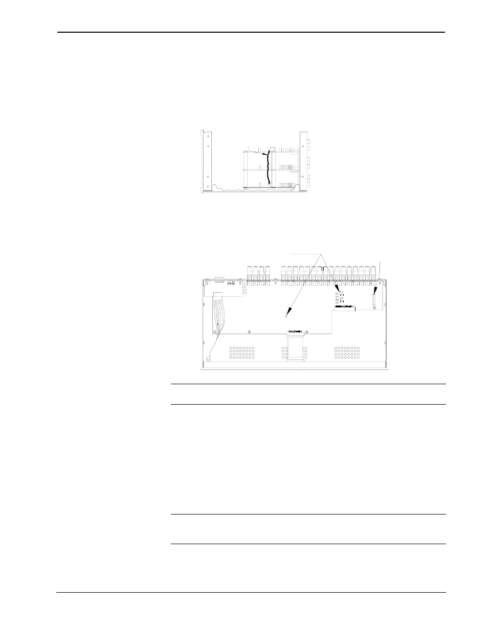
4. Use the supplied cable (15863) to connect board 1 (bottom board) to
board 3 (top board), as shown in the diagram that follows this step.
Location of Cable Connection (Side View of Unit)
USE CABLE FOR CONNECTION
OF LEVEL 1 TO LEVEL 3 ONLY
5. If the desired application requires removal of the jumpers, remove the
nine jumpers from level 3 (top board) only, as shown in the diagram
after this step. Otherwise, skip this step and step 6.
Location of Jumpers (Top View with Cover Removed)
JUMPER HOLDER
STORES REMOVED
JUMPERS
TO SPLIT LEVEL 3,
REMOVE NINE JUMPERS
(FROM LEVEL 3 ONLY)
NOTE: Eight of the nine jumpers are grouped together. Do not forget to remove the
ninth jumper that is located separately from the other eight.
6. Store jumpers removed in step 5 on the jumper holder, as shown in the
diagram that precedes this step.
7. Place the cover over the unit (observe proper orientation with respect to
front and back panels) and secure with 16 cover screws.
8. Tighten screws to finger-tight, then, using a #2 Phillips screwdriver,
tighten an additional 1/8-turn.
Rack Mounting
WARNING: To prevent bodily injury when mounting or servicing this unit in a
rack, take special precautions to ensure that the rack remains stable. The following
guidelines are provided to ensure user safety.