Assembly, Warning – Craftsman 247.88045 User Manual
Page 9
ASSEMBLY
Make certain the entire bottom surface of skid shoe is against the
ground to avoid uneven wear on the skid shoes.
Retighten nuts and bolts securely.
Testing auger Drive Control
When the auger control is released and in the disengaged “up” posi-
tion, the cable should have very little slack, but should NOT be tight.
In a well-ventilated area, start the snow thrower engine as
instructed in the Operation section. Make sure the throttle is set in
the fast position
.
While standing in the operator’s position (behind the snow
thrower), engage the auger control and allow the auger to remain
engaged for approximately ten seconds before releasing the
auger control. Repeat this several times.
With the engine running in the fast position
and the auger
control in the disengaged “up” position, walk to the front of the
machine. Confirm that the auger has completely stopped rotating
and shows no signs of motion.
If the auger shows any signs of rotating, immediately return to the
operator’s position and shut off the engine. Wait for all moving
parts to stop before readjusting the auger control cable.
Testing Drive Control & Shift Lever
Refer to Fig. 9 for location of controls.
Move the shift lever into sixth (6) position.
With the wheel drive control released, push the snow thrower
forward, then pull it back. The machine should move freely.
Engage the drive control and attempt to move the machine both
forward and back, resistance should be felt.
Move the shift lever into the fast reverse (R2) position and repeat
the previous two steps.
If you experienced resistance rolling the unit, either when repositioning
the shift lever from 6 to R2 or when attempting to move the machine
with the drive control released, adjust the drive control immediately.
See Adjusting Drive and Auger Controls.
adjusting Drive and auger Controls
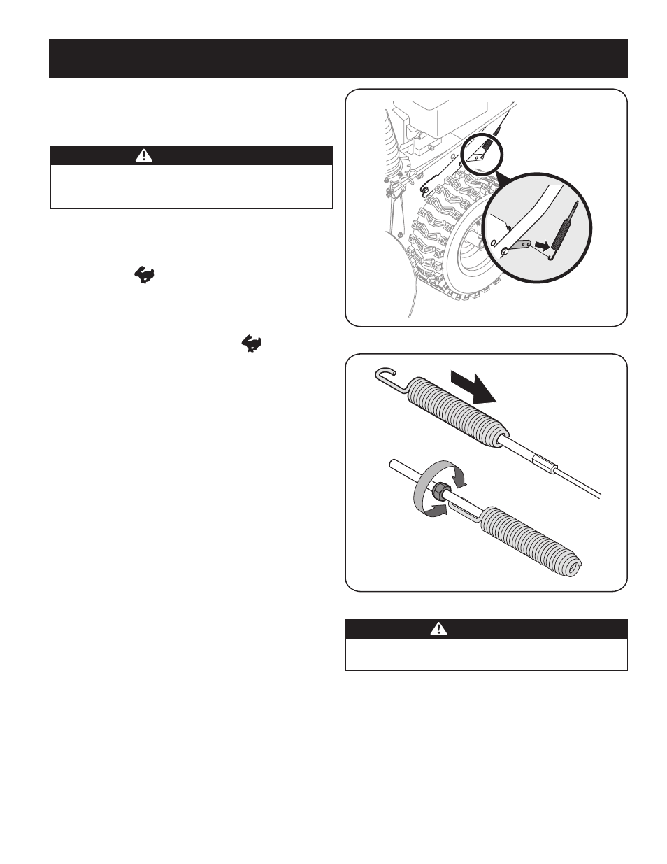
From beneath the handle, pull downward on the appropriate cable
and unhook the spring found on the end of the cable from its
respective actuator bracket. Refer to Fig.s 9 and 10.
Slide the spring up the cable to expose the cable coupler threads
and lock nut. Refer to Fig. 11.
If adjusting the drive cable, thread the lock nut outward (down the
coupler) to lengthen the cable and allow the unit to move freely
when the control is released. Thread the lock nut inward (up the
coupler) to shorten the cable to reduce slippage and prevent the
machine from being easily moved with the drive control engaged.
If adjusting the auger cable, thread the lock nut down to lengthen
the cable as necessary to stop the auger from turning when the
control is released.
2.
3.
1.
2.
3.
4.
1.
2.
3.
4.
1.
2.
3.
4.
Figure 10
Warning
Prior to operating your snow thrower, carefully read and follow all
instructions below. Perform all adjustments to verify your snow
thrower is operating safely and properly.
Figure 11
Warning
Do not over-tighten the cable. Over-tightening may prevent the auger
from disengaging and compromise the safety of the snow thrower.
Reattach the spring to the rearmost hole in the actuator bracket.
Repeat the wheel drive and auger control tests to verify proper
adjustment. Repeat previous steps if necessary to attain proper
adjustment of each cable.
5.
6.