Electrical connection, Awarning, Now start – Whirlpool 3149595 User Manual
Page 3
Attention! The text in this document has been recognized automatically. To view the original document, you can use the "Original mode".
F
a
3/4", U.L-listed strain relief
must be provided at the
" junction box.
G
it is the persohdi
■ responsibiiity and obiigation
of the customer to contact a
quaiified eiectrician to assure that
the eiectrioai instdiiation is adequate
and in conformance with the
National Eiectricdi Code ANSI/NFPA
70-idtest edition, and ali local codes
and ordinances.
’ Copies of the stondard listed may
be obtained from;
Notional fire Protection Association
Battery March Park
Quincy, Massachusetts 02169
H
A wiring diagram is included
■ in the Tech-sheet (located
behind the air grille) with
self-cleaning ovens. For other
models, the wiring diagram is
located on the back, right-hand side
of the oven.
Electrical
connection
Elecfhcal ground is required on this
appliance.
AWARNING
Electrical Shock Hazard
’ Do Not connect appliance to
electrical supply until appliance
is permanenlly grounded.
’ Disconnect power to the junction
box
before making the electrical
connection.
*
This appliance must be
connected to a grounded,
metallic, permanent wiring
system, or a grounding
conductor should be connected
to the grounding terminal or lead
on the appliance.
Failure to follow these instructions
could result in a fire, personal
injury, or electrical shock.
This appliance is manufactured with
the neutral (white) power supply
wire and a cabinet-connected
grounding wire (green) twisted
fogether.
Connect the appliance cable to the
junction box through the 3/4“,
U.L.-listed strain relief. Complete the
electrical connection according to
local codes and ordinonces.
A. Where local codes permit...
Connectihg the cabinet-grounding
conductor to the neutral (white)
junction box wire:
1. Connect together three wires: the
green (or bare) and white appliance
cable wires with the neutral (white)
wire in the junction box,
2. Connect the two black wires; then
the two red wires, (See Figure 1,)
B. Where local codes Do Not
permil...
Connecting the cabinet-grounding
conductor to the neutral (white)
junction box wire:
1. Separate the green (or bare) and
white appliance cable wires.
2. Connect the white appliance
cable wire with the neutral (white)
wire in the junction box,
3. Connect the two black wires;
then connect the two red wires.
(See Figure 2 )
4. Connect the grounding wire to a
grounded wire in the junction box
or to a grounded, copper, cold
water pipe’.
Copper
Tlghlen
nuts firmly. J '
Grounded cold
water pipe
' —
(remove paint etc,)
Melai cold
water pipe
A
6. A separate, copper grounding
wire (No. 10 minimum) must be
connected to a grounded, cold
water pipe by means of a clamp
and then to the external grounding
connector screw. Do Not ground to
a gas supply pipe or hot water pipe.
Do Not connect to the electrical
supply until appliance is
permanently grounded,
* Grouniped cold water pipe must have
mefol continuity to electrical ground and not
be interrupted by plastic, rubber or other
electrical insulating connectors such as
hoses, fiftings, wosners or gaskets (including
water meter or pump). Any electrical
insulating connector should be jumped, as
shown, with o length of No 4 copper v/ire
securely clampea to bare metal al both
ends.
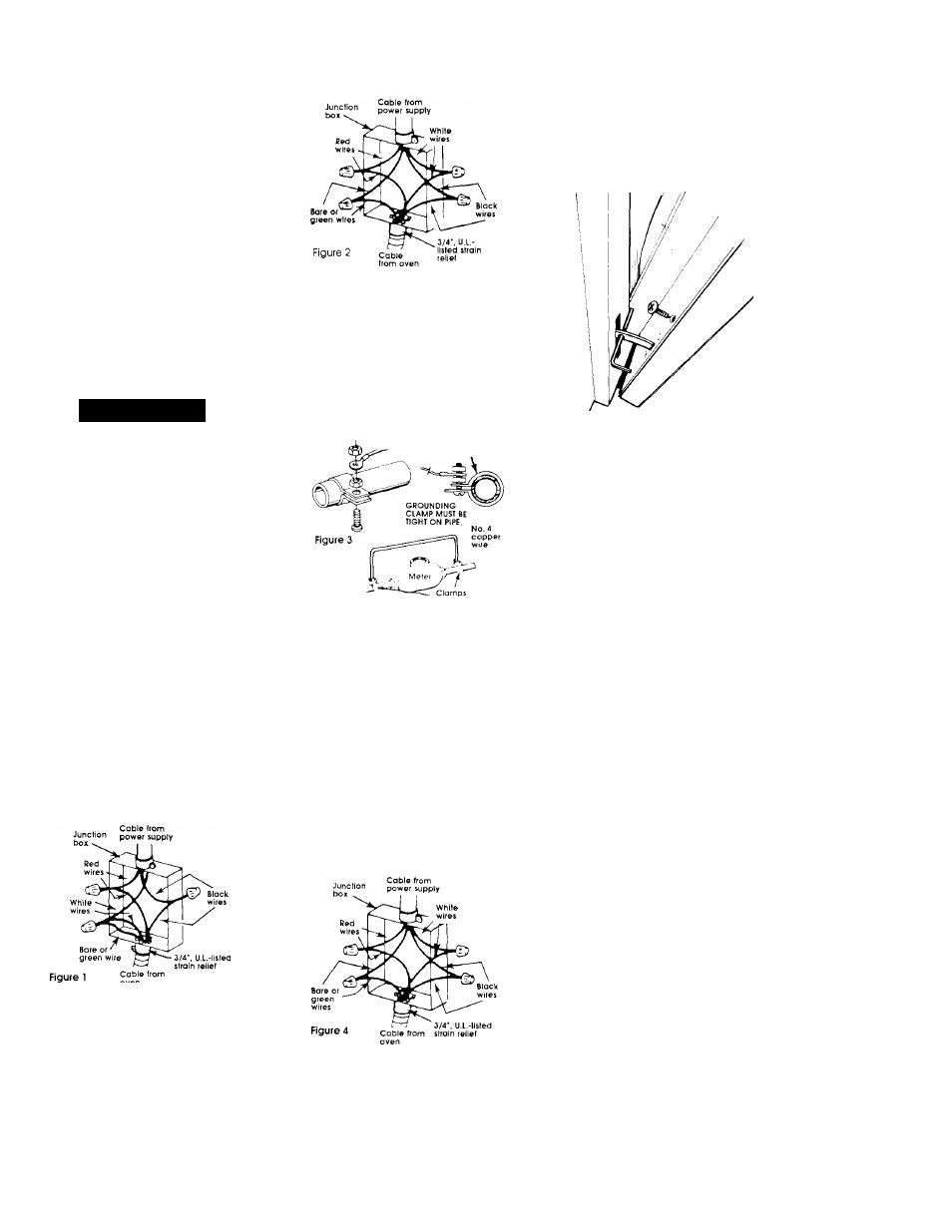
C. If connecting to a tour-wire
electrical system...
Do Not cohhect the cobihet-
grouhding conductor to the neutral
(white) wire in the junction box.
1. Separate the green (or bore) and
white appliance cable wires.
2. Connect the white oppliance
cable wire to the neutral (white)
wire in the junction box,
3. Connect the two black wires; then
connect the two red wires, (See
Figure 4.)
4. Connect the green appliance
cable wire to the green grounding
wire in the junction box
Now start...
With oven in kitchen...
1
Remove shipping materials,
■ tape and protective film from
oven. Do Not remove the shipping
base at this time.
2
Remove the racks and
■ other ports from inside the
oven. Remove the dir grille taped to
the top or side of the oven.
3
Upper oven door: Remove
■ the screws on each side of
the inner panel of the oven door.
Insert a nail (or an equivalent. 5/32"
diameter item) into the hole In each
of the hinges. Close the door as far
as possible. Lift the oven door off of
the hinges. Set aside.
Lower oven door: Open the oven
door to the broil '"stop" position and
lift door upwards to remove. Set
oven door aside.
Panel B