Fcu utility fans, Standard features & benefits, Accessories / options – CFM FCU-20 User Manual
Page 2: Arrangement 10, swsi, class i
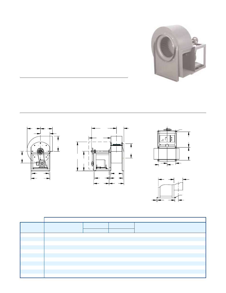
FCU UTILITY FANS
2
V-DIA.- 6 HOLES
FOUNDATION LAYOUT
V-DIA.- 4 HOLES
BASE DETAIL SIZES 8, 9, & 11
K
L
J
C
H
A
F
M
N
T
D
Q
E
B
R
X
S
P
Q
E
F/2
F/2
B
D
Y
E
5/8
Note:
• Letters “C” and “D” are outside housing dimensions.
• “C” dimension extends beyond center-line, size #8 (5/16), size #9 (1-9/16) & size #11 (1-1/16)
MODEL
WHEEL
DIA.
SHAFT
DIA.
TH, DB, BH, UB
STRAIGHT DISCHARGE
BAU, TAU, TAD, BAD
ANGULAR DISCHARGE
MAX.
MTR
FRAME
A
B
C
D
E
F
H
J
K
L
H
J
K
L
M
N
P
Q
R
S
T
V
X
Y
FCU-08
7.75
0.75
9.1 13.0
8.3
5.4 14.3
7.5
6.0
4.6
6.8
6.9 10.4
6.3
7.4
5.3 20.1
3.8
8.0
-
-
18.0 18.5
0.4
12.0
2.2
145T
FCU-09
9.00
0.75
10.4 13.0 10.8
6.5 14.3
8.4
6.8
5.6
7.8
7.1
11.6
7.5
8.3
6.1 20.8
4.3
9.0
-
-
18.0 18.5
0.4
12.0
2.8
145T
FCU-11 10.50
1.00
12.9 13.0
11.8
8.0 14.3 10.8
7.9
6.8
9.1
8.1 13.3
8.9
9.6
7.1 21.5
5.1 10.0
-
-
20.5 18.5
0.4
14.0
3.5
145T
FCU-12 12.25
1.00
16.4 13.5 13.3
9.6 13.5 14.8 10.1
8.5
11.5 10.5 16.6 10.8 12.5
9.1 23.9
6.4 13.3
11.3 12.8 25.3 20.0
0.5
17.0
-
182T
FCU-13 13.50
1.00
17.6 13.5 14.6 10.8 13.5 16.0
11.1
9.4 12.6
11.4 18.3
11.9 13.8 10.0 24.4
7.0 14.5 12.4 13.9 25.9 20.0
0.5
17.0
-
182T
FCU-15 15.00
1.00
19.3 15.5 16.3
11.8 15.5 17.6 12.4 10.4 14.1 12.4 20.1 13.3 15.3
11.1 26.9
7.5 16.1 13.4 14.9 27.6 22.0
0.5
17.9
-
182T
FCU-16 16.25
1.00
21.4 15.0 17.8 13.0 15.5 19.8 13.6
11.4 15.5 13.4 21.9 14.6 16.8 12.3 27.5
8.5 17.9 14.5 17.0 30.1 22.0
0.5
19.5
-
184T
FCU-18 18.25
1.19
23.1 17.0 19.6 14.3 17.5 21.5 15.0 12.6 17.1 14.6 24.1 16.0 18.5 13.6 30.6
9.1 19.6 15.8 18.3 33.4 25.0
0.5
21.9
-
184T
FCU-20 20.00
1.19
25.0 17.0 21.5 15.9 17.0 23.4 16.5 13.8 18.8 15.8 26.4 17.6 20.4 14.9 31.5 10.0 21.5 17.9 20.1 36.3 25.0
0.5
23.8
-
213T
FCU-22 22.25
1.19
27.4 16.5 24.0 17.4 17.0 25.8 18.3 15.3 20.9 17.3 29.0 19.5 22.6 16.5 32.8 10.6 23.9 19.4 22.6 39.8 26.0
0.5
26.1
-
213T
FCU-24 24.50
1.44
30.3 16.5 26.3 19.3 16.8 23.6 20.1 16.9 23.0 19.9 32.5 21.5 24.9 18.3 33.6 11.8 26.4 21.3 24.5 42.9 26.0
0.5
27.8
-
215T
*DO NOT USE FOR CONSTRUCTION
CONSULT FACTORY FOR CERTIFIED PRINTS
DIMENSIONS IN INCHES*
STANDARD FEATURES & BENEFITS
•
Heavy gauge, rugged welded steel construction
•
Forward curved impeller
•
Self-aligning pillow block bearings
Standard bearings have 100,000 hours average life
•
CW & CCW rotation
•
Discharge rotatable to 8 positions
•
Rigid circular stamped inlet ring
•
Adjustable V-belt drive
•
TEFC industrial duty motor
•
AMCA Class I construction
ACCESSORIES / OPTIONS
• Belt
guard
•
Flanged inlets & outlets
•
Drain fitting
•
Protective coatings
•
Heat slinger
•
Automatic discharge shutter
•
Weather cover / drive cover
•
Inspection doors (bolted or quick opening)
•
Inlet & discharge screen
•
Vibration rail base (spring rail or RIS rail)
•
AMCA Type A, B & C construction
•
Explosion proof & special duty motors
ARRANGEMENT 10, SWSI, CLASS I