2205 p2.pdf – Braeburn 220550 User Manual
Page 2
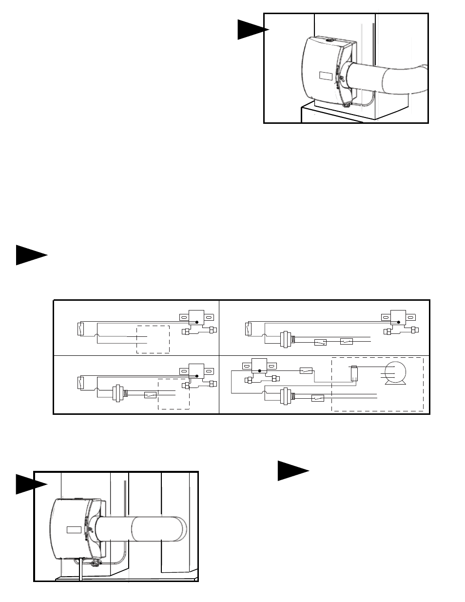
5
Connect 1/4" water supply tube to brass filter at inlet of solenoid.
DO NOT USE PLASTIC TUBING IN CONTACT WITH ANY
HOT PLENUM SURFACE OR DUCT. IF USING PLASTIC
TUBING, USE INSERT FOR PLASTIC TUBING AND
PLASTIC COMPRESSION SLEEVE (INCLUDED WITH
SADDLE VALVE KIT).
Turn damper knob to winter (open) position.
Turn on water supply and check operation of
humidifier. Set humidistat to a demand setting. With
the furnace off, the solenoid valve should be closed.
Start the furnace. The solenoid valve should open
when the blower or burner circuit is energized.
Check flow of water through distributor trough and
evaporator pad. The standard yellow orifice will
supply approximately 3.5 GPH of water at a line
water pressure of 60 psi. Leave humidistat set at the
recommended setting.
Connect drain hose to
1/2"
spout
on
humidifier
cabinet
using hose clamp.
Run 1/2" hose to
suitable drain such as
floor drain, sewer or
laundry sink. Be sure
hose has continuous
slope and is not kinked
at any point.
8
6
HUMIDISTAT
WIRING
PLEASE SEE COMPLETE SET OF INSTRUCTIONS SUPPLIED WITH HUMIDISTAT
7
ACC
EAC
(HOT)
C
115v.
60CY.
ON-OFF SWITCH
COMMON LEAD
FURNACE
C
HI
LO
229050
CURRENT
SENSING
RELAY
MULTI
SPEED
BLOWER
MOTOR
24V. SOLENOID VALVE
HUMIDISTAT
24 V. TRANSFORMER
ACC
EAC
(HOT)
C
115v.
60CY.
ON-OFF SWITCH
24V. SOLENOID VALVE
24V. SOLENOID VALVE
24 V. TRANSFORMER
L1
C
NO
(HOT)
L2
115v.
60CY.
ON-OFF SWITCH
AIR PRESSURE
SWITCH
24 V. TRANSFORMER
HUM
FURNACE
CONTROL BOARD
C
24v.
60CY.
24V. SOLENOID VALVE
HUMIDISTAT
HUMIDISTAT
HUMIDISTAT
FURNACE
BOARD
PRECAUTIONS
The installer should be a qualified Technician. Disconnect electrical power before beginning installation. Install
the humidistat on the return duct using the foam gasket. Conduct a thorough checkout before leaving the
installation.
THE BRAEBURN
®
220500 INCLUDES MANUAL HUMIDISTAT (MODEL 229100)
THE BRAEBURN
®
220550 INCLUDES DIGITAL HUMIDISTAT (MODEL 229150)
SADDLE VALVE INSTALLATION INSTRUCTIONS
Copper Pipe
1. Retract piercing pin into valve body by turning handle counterclockwise.
2. Screw valve body into upper bracket and tighten.
3. Place rubber gasket over piercing pin.
4. Assemble saddle valve over copper pipe using enclosed screws,
nuts and lower bracket.
5. Tighten screws evenly and firmly. Brackets should be parallel.
6. Complete compression connection to saddle valve outlet.
7. Turn handle clockwise to pierce tubing and close saddle valve.
8. Turn handle counterclockwise to open saddle valve. Leave open for several
seconds to flush dirt from pipe and tubing.
Steel, Brass or Hard Plastic Pipe
1. Shut off water supply and drain the water from the supply pipe.
2. Turn handle clockwise to expose piercing pin and close saddle valve.
3. Place rubber gasket over piercing pin.
4. Drill 1/8" hole in pipe using a hand crank drill to reduce shock hazard.
5. Assemble saddle valve over steel, brass or hard plastic pipe using enclosed
screws, nuts and lower bracket.
6. Tighten screws evenly and firmly. Brackets should be parallel.
7. Complete compression connection to saddle valve outlet.
8. Turn handle counterclockwise to open saddle valve. Leave open for several
seconds to flush dirt from pipe and tubing.
Threaded Pipe Fittings
1. Turn handle clockwise to expose piercing pin and close saddle valve.
2. Seal valve body threads using pipe tape or sealant.
3. Install valve into 1/8" NPT fitting.
4. Complete compression connection to saddle valve outlet.
5. Turn handle counterclockwise to open saddle valve. Leave open for several
seconds to flush dirt from pipe and tubing.