3 input sensitivity adjustment, 4 additional load protection, 5 required ac mains – Crown POWER BASE 3 User Manual
Page 10: When set to 26 db gain, the power base-1, Requires a 2.0 volt input, the power base-2, Requires a 2.5 volt in- put and the power base-3, Power base series power amplifiers page 10, Fig. 2.4 input sensitivity switch, Fig. 2.5 loudspeaker fuse nomograph
Power Base Series Power Amplifiers
Page 10
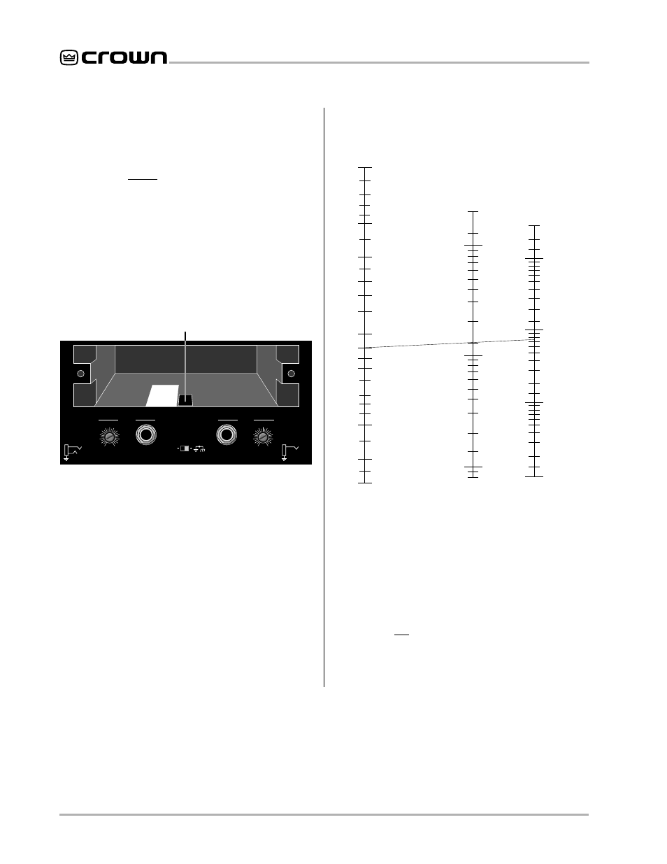
2.3 Input Sensitivity Adjustment
The input sensitivity switch inside the amplifier is set to
0.775 volts at the factory. It can be changed to 1.4 volts
or a voltage gain of 26 dB as follows:
1. Turn off and unplug the amplifier from the AC source.
2. Remove the access cover on the back panel.
3. Locate the labeled access hole for the sensitivity switch.
4. Set the switch to the desired position.
5. Replace the access cover plate.
When set to 26 dB gain, the
Power Base-1
®
requires a
2.0 volt input, the
Power Base-2
®
requires a 2.5 volt in-
put and the
Power Base-3
™
requires a 3.2 volt input to
deliver full output into an 8 ohm load.
0.77 V
26 dB
SENSITIVITY SWITCH INSIDE ACCESS HOLE
1.4 V
THIS AMPLIFIER IS EQUIPPED WITH SELECTABLE INPUT SENSITIVITY. REMOVE COVER PLATE (ABOVE) TO ACCESS SENSITIVITY SWITCH.
CH-2
INPUT GROUND LIFT
(AFFECTS PHONE INPUTS ONLY.)
(MONO)
INPUT
GAIN
CH-1
INPUT
GAIN
LIFT
BALANCED
INPUT WIRING
+
–
TIP
RING
SLEEVE
GND
UNBALANCED
INPUT WIRING
+
TIP
SLEEVE
GND
0
1
2
3
4
5
6
7
8
9
10
11
12
0
1
2
3
4
5
6
7
8
9
10
11
12
Fig. 2.4 Input Sensitivity Switch
2.4 Additional Load Protection
To protect against excessive power, a fuse can be
added in series with each loudspeaker cable. A single
fuse can protect the entire system, or one can be used
for each driver. High-frequency drivers (tweeters) are
usually more sensitive to large voltage peaks, while
low-frequency drivers (woofers) are typically most sen-
sitive to the heat from average (RMS) output power. To
protect your tweeters, we recommend that you use a
high-speed instrument fuse like the Littlefuse 361000
series. To protect your woofers, we recommend using a
slow-blow fuse that more closely represents the thermal
response of your woofer. Use Figure 2.5 to find the cor-
rect value for either type of fuse.
Example: (A) Find the peak music power of your loudspeaker
(such as 75 watts). (B) Find the loudspeaker impedance (8
ohms). (C) Draw a line between points A and B. The line inter-
sects the middle scale at the correct fuse value (1.5 amps).
1.0
1.2
1.4
1.6
2.5
3
4
5
6
7
8
9
10
12
14
16
20
25
30
20
15
10
8
6
5
4
3
2
1.5
1
.8
.6
.5
.4
.3
.2
.15
.1
.08
3000
2000
1500
1000
800
600
400
300
200
150
100
80
60
40
30
20
15
10
8
6
4
3
2
1.5
1
LOUDSPEAKER IMPEDANCE
(ohms)
FUSE
(amps)
LOUDSPEAKER RATING
PEAK MUSIC POWER
(watts)
(Typically 4 times the continuous average power)
Answer: Fuse = 1.5 A
2
40
Example:
Impedance = 8 ohms.
Peak Power = 75 W
Fig. 2.5 Loudspeaker Fuse Nomograph
2.5 Required AC Mains
All
Power Base amplifiers are shipped with an appro-
priate line cord and plug. When possible, use a power
receptacle on a dedicated circuit, and always make
sure it will provide the right voltage and sufficient cur-
rent. We do not recommend operating your amplifier
with voltages greater than 10% above or below the
unit’s rated voltage. For example, if your amplifier is
rated for 120 VAC, the line voltage should not exceed
132 VAC.