Gate control unit, Program, Gate control unit (gcu) (not provided) – Chamberlain LIFTMASTER MUGAPLM User Manual
Page 2: Assemble, Installation
2
Gate Control Unit (GCU)
(not provided)
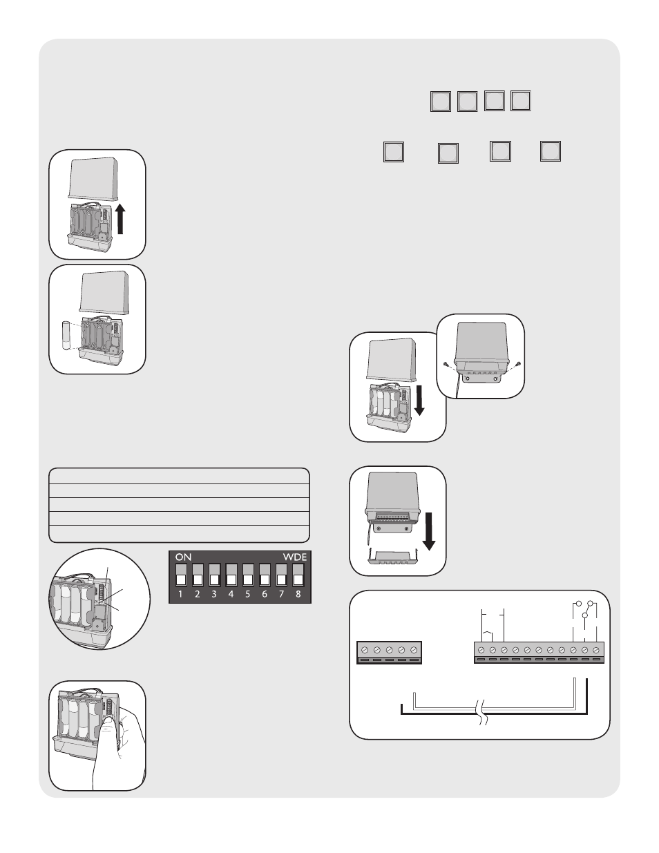
Assemble
Step 1: Remove GCU cover.
Step 2: Install 4 AA Alkaline
batteries (not provided).
(Lithium batteries
recommended for colder
environments.)
NOTE: This step applies only if more than one GCU
is being used.
Step 3: Up to four GCUs can be used. Each GCU will
need a different Identity. Set the Identity of the GCU
by changing the Dipswitches as shown in the chart
below.
GCU ID
Switch #1
Switch #2
1
OFF
OFF
2
ON
OFF
3
OFF
ON
4
ON
ON
Dipswitches
Learn
Button
Program
Press the Learn button on the
GCU for one second. The LED
will light for 20 seconds.
LED
?
?
?
?
Within 20 seconds enter Master PIN Number on
MUGAPLM:
Followed by GCU Identity as determined in Step 3:
1
2
3
4
OR
OR
OR
The GCU LED will blink 3 times indicating
programming is successful. NOTE: The relay will
engage. If error tone is heard or GCU LED emits 3
double blinks, then programming has failed.
Repeat for additional GCUs.
Installation
Step 1: Replace GCU cover
and mount near gate operator
control box.
Step 2: Remove bottom panel
of GCU. Connect Terminal 10
on GCU to Common on gate
operator (shown below).
Connect Terminal 9 to Cycle on
gate operator (shown below).
“BEEP” “BEEP”
NOTE: If there is already an existing receiver proceed
to Pre-Installed LiftMaster Receiver
(315Mhz Only) section.
1
3
2
4
5
6
7
8
9 10 11
DC
AC
+
-
COM
N/C
EXIT
SAFETY
EDGE
COMMON
OPEN
N/O
GATE OPERATOR
GCU