Ope r ator, Ope r ator wir ing diagr am – American Access Systems Advantage DKE - Single Gang - 26-100SG User Manual
Page 4
Page 4 American Access Systems / Security Brands, Inc.
STEP 1-MOUNTING THE UNIT
Page 3 tells you what tools and instruments you will need to install your unit and presents a parts check list. Make sure
to have all the tools listed. Upon opening the box, check off the items enclosed with the unit. If any items are missing
from your unit, contact American Access Systems immediately.
The ADV-100sg is designed to mount in a standard 2 x 4 electrical box. Two security screws are provided to prevent
tampering. American Access Systems can provide the proper tool to install these screws for a additional cost. They
are standard (snake eyes) screws.
Once you have made your connections, fold the wires into the box and secure the keypad being careful not to
pinch any wires between the box and keypad panel.
STEP 2-SYSTEM CONNECTIONS
Study the WIRING COLOR CODE chart below and then proceed to the hookup steps.
WIRING COLOR CODES
WHITE(AC Hot)(DC +)
12 - 24 VOLTS
WHITE(AC Neutral)
(DC -)
AC or DC
LATCH CONTACTS
BROWN
RELAY COMMON
ORANGE
NORMALLY OPEN
BLUE
NORMALLY CLOSED
HOOKUP STEPS
(A). Your DKLP control unit operates on 12 to 24 volts AC or DC. Measure the voltage from the power source to
make sure it falls within these tolerances. Locate the two white wires on the circuit board and with the power off
connect them to a constant power supply.
(B). Connect the device to be controlled to the appropriate control leads of the ADV-100 (See above diagram).
(C). Double Check your connections. When you are sure that everything is hooked up correctly, apply power to the
unit. A BEEP should be heard when you press a key on the keypad.
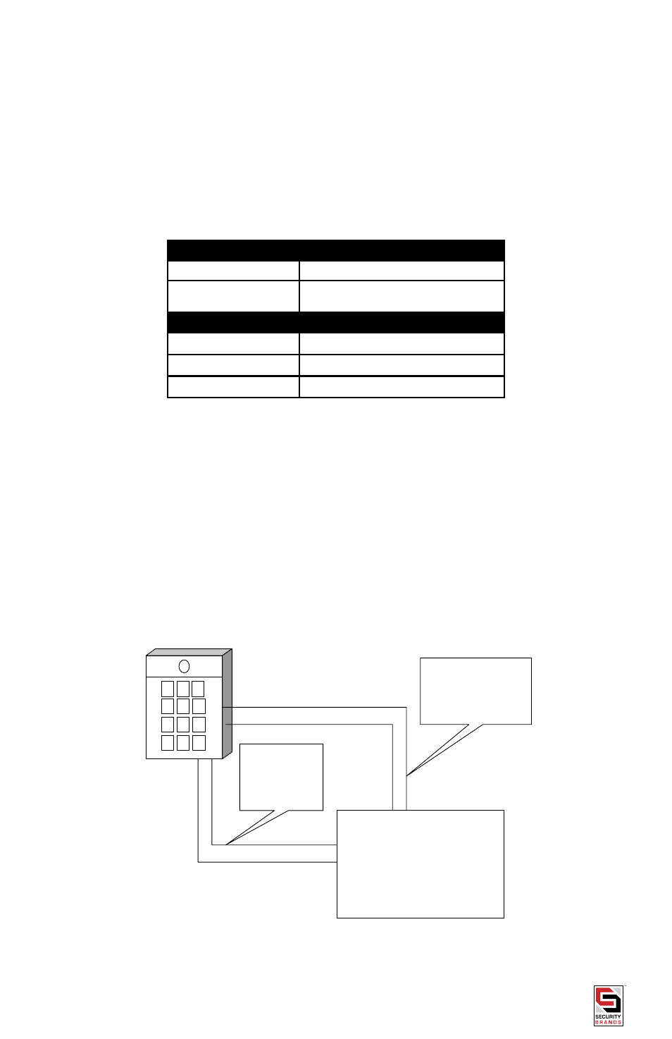
OPE R ATOR
White/White connect to
operator secondary power.
(12 to 24 volt)
Orange/Brown
connect to operator
open/close circuit.
(Blue not used)
OPE R ATOR WIR ING DIAGR AM