Chamberlain DC2000 User Manual
Dc2000 back-up wiring for the omnicontrol™ board, Safety options, Emergency override
1
3
2
7
6
5
4
Strike Open
Push Button
Strike Open
Push Button
24 Volts DC
24 Volts DC
Fire Dept
Key Switch
Fire Dept
Key Switch
M/S Link
M/S Link
Class 2
Supply
Class 2
Supply
Center
Loop
Center
Loop
Safety
Loop
Safety
Loop
Radio
Receiver
Radio
Receiver
Exit
Loop
Exit
Loop
G
G
B
B
A
A
+
+
OmniControl Surge Suppressor
P/N Q410
Patent Pending
P/N Q410
Patent Pending
CENTER
SAFETY
EXIT
CENTER
SAFETY
EXIT
FIRE
DEPT.
1
3
STRIKE
OPEN
RADIO
RECEIVER
TIMER
SYSTEM ON
EXIT
LOOP
ALARM
SENSOR
REVERSE
SENSOR
OPEN
STOP
CLOSE
SAFETY
LOOP
CENTER
LOOP
GATE
LOCKED
60
POWER
OVERLOAD
OFF
W4
OPEN LEFT
DC-BACKUP
ALARM
SENSOR
OPEN RIGHT
3
SENSORS
RESET
MOTOR
1
3
1
3
COMMAND
PROCESSED
ON
G B
MS LINK
A
MADE IN CHINA
OFF
ON
CHASSIS
GROUND
12 13
11
CAUTION
Black 120 Vac
White Neutral
Green Ground
OPEN
STOP
LOSE
POWER
OVERLOAD
MADE IN CHINA
CLO
A
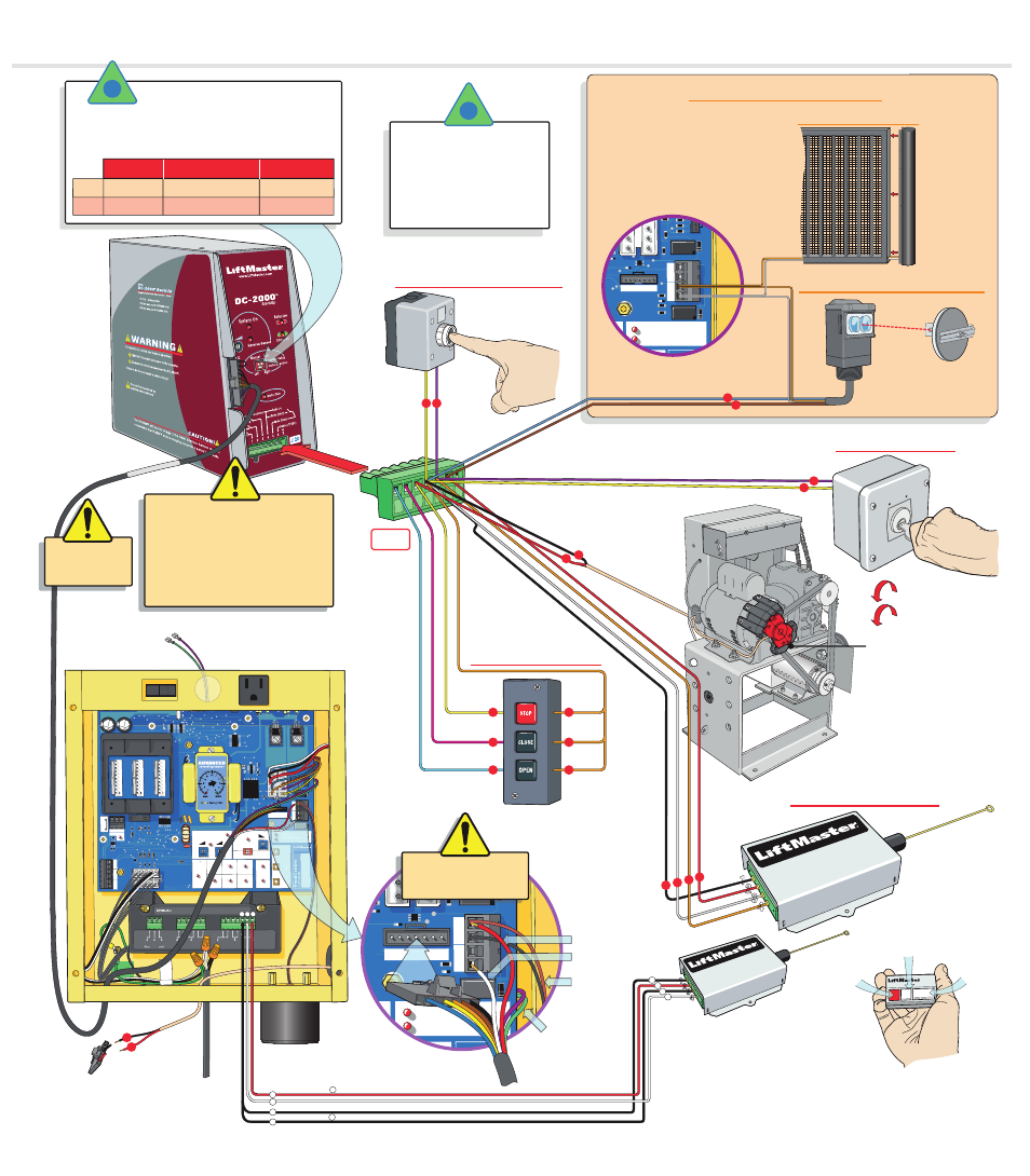
Push and
“Hold”
a Button to operate
“Optional Manual One-Button”
“Optional Three-Button”
Socket
“Optional Edge Sensor”
“Optional Radio Receivers”
“Optional Key Switch”
OmniControl™ Board
Sensor Connection
Push and
“Hold”
to Open
Push again and
“Hold”
to Close
Turn and
“Hold”
to Open
Turn again and
“Hold”
to Close
POWER
OVERLOAD
DC-BACKUP
ALARM
SENSOR
1
3
2
4 5
6
4
N.O.
N.O.
N.O.
USE ONLY 12 VDC FAILSAFE PHOTOCELL
SENSORS FOR THIS SAFETY OPTION
Failsafe Photocell: If a photocell is not
working or loses power or photo beam is
blocked, then the photocell will stop all gate
operation.
“Optional Photocell Sensor” 12 VDC
Interlock
Assembly
5
4
1
2
3
4
Com
Com
Com
4
5
SAFETY OPTIONS
DC2000 Back-Up Wiring for the OmniControl™ Board
with Optional Equipment
Power +12 VDC
Power Ground
Part #
AEXITP
Part #
AEXITP
Part #
A1KX
Part #
A1KX
Part #
312HM
Part #
312HM
Part #
373LM
Part #
373LM
Part #
AOMRON12V
AOMRON12V
4
4
4
4
If the DC2000 is automatically opening the gate
due to a power failure, any manual command such
as
“Manual One-Button”
,
“Three Push Button”
,
“Key Switch”
,
“Photocell”
or
“Edge Sensor”
will
cancel the
automatic mode
of the DC2000. After
such cancellation, the DC2000 will continue to
operate in
manual mode
until 115 Vac power is
restored.
If 115 Vac power is on, but the system has
an electronic malfunction, the gate can be
operated using the DC2000 system with
ANY
of these devices shown.
EMERGENCY
OVERRIDE
J5
POWER
OVERLOAD
DC-BACKUP
ALARM
SENSOR
BACK
CK
-B
DC2000 Harness
Red Wire
White Wire
J5
Green and Purple wires
wrap behind board to
the limit switches
Audio Alarm
Wires
DO NOT remove existing wires
from the audio alarm or
secondary protection sensor.
“Manual”
setting:
The DC2000 will respond to the input devices wired to the J 20 socket.
This mode can also be used as an emergency override. If 115 Vac power is on, but the system has an electronic
malfunction, the gate can be operated using the DC2000 system with input devices wired to J 20 socket.
“Auto”
setting:
The DC2000 opens the gate automatically upon 115 Vac power failure and stays open. When 115
Vac power is restored, the gate operator will return to normal operation. (The gate can be closed by manual
command)
System Setup
Manual
Mode
Auto
Mode
Push and
Hold
to
operate gate
115 Vac Power
Failure
115 Vac Power On,
OmniControl Board™ Malfunction
115 Vac Power On,
Emergency Override
Gate automatically
opens
Turn the 115 Vac power off then
push and
Hold
to operate gate
Push and
Hold
to override
the OmniControl™ Board
Push and
Hold
to override
the OmniControl™ Board
Turn the 115 Vac power off then
gate opens automatically
For Technical Support
and Ordering Parts:
1-800-528-2806
OPEN CLOSE
DO NOT wire
115 Vac power
to the DC2000
DC20
00 Ha
rness
Jumper P3:
to 12 Volt
Jumper P2:
to Constant (C)
Button One:
Normal Gate
Operation
(OmniControl™ Board)
Button Two:
Back-Up Operation
(DC2000)
Button Three:
Optional Accessories
Push and
“Hold”
DC2000 Remote Button to Open
Push again and
“Hold”
DC2000 Remote Button to Close
6
3
4
Refer to Receiver
Manual for Further
Details about settings.
Button One:
Normal Gate Operation Only
(OmniControl™ Board)
Separate
12 VDC
DC2000 Radio Receiver
Interlock Assembly Wire
4
3
Factory installed
Interlock Assembly
Wires to J20 Socket
Cut and
Discard Plug
To Limit Switches
Radio Receiver +
Radio Receiver -
13
11
11
12
24 VDC
Factory Installed
Radio Receiver
1
2
3
11
11
13
4
12
J 20