Acronova NB15-BR Series User Manual
Acronova Equipment
User’s Manual, Nimbie NB15, ver. 9A2, Part #: 711-NB15-9AC6-1
User’s Manual
Client Unit, Nimbie Chorus
Expandable Automated Disc
Duplicating System
(Model: NB15/NB15-BR Series)
I
MPORTANT
S
AFETY
I
NSTRUCTIONS
For your safety, basic precautions should always be followed to reduce risk
or damage, electric shock, fire, and personal injury. This includes the
following:
Read this manual carefully and follow all warnings and instructions.
Do not expose this unit to direct sunlight, rain, moisture, water,
flammable materials, gas, dust, dirt, smoke, pollution or abrupt humidity
changes.
Place this device on a steady level surface in an air-conditioned
environment with sufficient ventilation. Do not move this device while
the power is on. Handle with care.
This device generates heat during the duplication process.
Out-of-specification or unstable power supply may cause overheating,
low productivity, increased failure rate, and damage to the device.
Only use the NimbieCable that comes with your unit to connect the
NB15 (Client unit) to the NBCH07 (Master unit).
Do not attempt to disassemble this device or touch any of the moving
parts. Refer to qualified service personnel. Unauthorized disassembly
or repair will void all warranty.
P
REFACE
Congratulations on purchasing Nimbie NB15, a Client unit to connect with
Nimbie Chorus Master unit (NBCH07) for multiple-drive optical disc
duplication operation.
Nimbie NB15 is an integrated device with built-in optical disc recorder and
autoloaders. Depending on the model of your purchase, it may come with a
CD/DVD (NB15) or Blu-ray recorder (NB15-BR). Its enclosure protects 30
discs from dust. With the lid open and the extension rods attached, it has
100-disc capacity. During operation session Nimbie NB15 can detect faulty
discs and reject them to the bottom of the unit.
Please read this manual carefully to understand the basic operations and
maintenance before using Nimbie NB15. For functional operation, refer to
the user's manual of Nimbie Chorus Master unit.
U
NPACKING
N
IMBIE
NB15
Before opening the package, carefully inspect for any damage. If there is
any sign of damage, contact the shipping company and your local dealer
immediately.
Save the packing materials in case you need to ship or return your product.
The original packaging will ensure the product is protected during
transportation. Returning goods without the original packaging may not
protect the product during transportation, and will void your warranty.
Package Contents
The items listed below should be included in the package:
One Nimbie NB15 (or NB15-BR) unit
One NimbieCable (connecting NB15 to a Nimbie Chorus Master unit)
One spindle box (serves as the Finish Disc Bin)
Three extension rods (attached to the underside of Nimbie's lid)
One alignment pad (serves to locate the Finish Disc Bin)
Four detachable legs (serves to raise Nimbie unit for the room of discs)
This operation manual
A
L
OOK OF
N
IMBIE
NB15
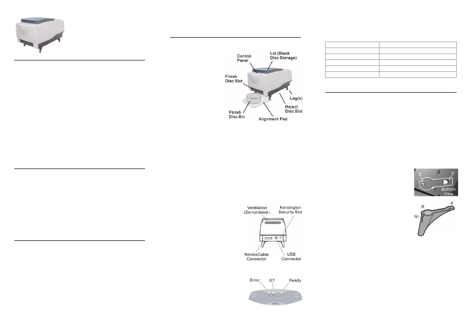
The figure to the right shows Nimbie with a spindle box in front of it to collect
and stack finished discs.
Lid (Blank Disc Storage)
Open the lid to access
the blank disc storage
area.
Control
Panel
Located on the top front
of Nimbie, the control
panel contains the LED
indicators and operation
buttons.
Detachable
Legs
Use the four legs
included with your
Nimbie to provide space
underneath for rejected discs.
Reject Disc Slot
Rejected discs will slide out from the Reject Disc Slot to the bottom of
the unit. Always allow space beneath Nimbie to accommodate rejected
discs.
Finish
Disc
Slot
Finished discs will exit from this slot.
Finish
Disc
Bin
This bin serves as the storage container for receiving and stacking
completed discs. As illustrated, a spindle box serves as a Finish Disc
Bin.
Alignment
Pad
Use the pad to appropriately position the Finish Disc Bin under the
Finish Disc Slot.
The Rear View
NimbieCable
Connector
Plug one end of NimbieCable to this
connector and plug the other end to
the Master unit.
USB
Connector
Reserved for firmware upgrade
purpose only.
Ventilation
Allow heat to release. Do not block
these holes otherwise the burning
quality may decrease or the unit
may overheat or damaged.
Kensington Security Slot
Security lock anti-theft system.
The Control Panel
There are operation buttons and LED
indicators on Nimbie NB15's control panel
as illustrated to the right. The Load/Unload
buttons are currently reserved for future
use.
LED Indicator Definitions
The LED indicator shows the Nimbie NB15's current status. When turned
on, Nimbie will enter initialization indicated by a flashing green ready light.
When initialization is complete, the ready light will change to steady green.
The table below describes the meanings of the LED indicator.
Error
GT
Ready
Description of the current status
Power off
Device Initialization
Ready
No Disc in Loader
Error
: Lit
: Off
: Flash
: Running
N
IMBIE
NB15
I
NSTALLATION
Finding a Place for Nimbie
Nimbie should be placed on a fairly level surface, firm enough to support
the unit and discs. Always allow ample workspace for your operation, with
easy access to the blank and finished discs.
Do not expose the unit to direct sunlight or high humidity, as it may cause
the unit to malfunction.
Nimbie can be placed on a raised block to process 100 or more discs in one
session. See the “More Than 30 Discs in One Session” section.
Using the Detachable Legs
Nimbie is designed to work either with or without detachable legs. Without
the legs, the Reject Disc Slot (recession) on Nimbie’s base will hold up to 3
rejected discs.
If your application doesn’t involve rejected discs,
you may use Nimbie without the legs. It is,
however, recommended to use the legs when
possible.
The legs will raise Nimbie and provide a
sufficient room to accommodate additional
rejected discs, and to get easier access to
rejected discs as well.
Attaching legs to Nimbie is simple. Inserting one
leg after another on Nimbie’s base, match the
leg to Nimbie (A to A’) and gently snap the leg
into the receptacle (B to B’) until it is firmly
attached.
To remove the legs, gently press the notch (N)
and pull it outward from the receptacle (B’).
Nimbie Hardware Installation
Follow the steps below to complete Nimbie's hardware installation:
1)
Place Nimbie on level surface so that it stands firmly on its legs.
2)
Place the spindle box that comes with the unit in front of Nimbie. Use
the alignment pad to appropriately position the spindle box under the
Finish Disc Slot.
3)
Use the NimbieCable that comes with the unit to connect Nimbie to
the Nimbie Chorus Master unit.
You have now successfully completed the installation of Nimbie device.