Kistler-Morse KM Microcell Bolt-On User Manual
Page 10
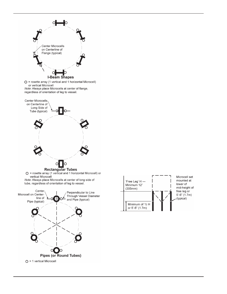
Figure 3-3. Microcell™ Mounting Arrangements on Legs.
HORIZONTAL DISTRIBUTION OF
MICROCELL™ SETS
Microcell™ sets are placed on each support leg.
Refer to Figure 3-3 for the mounting locations for
each shape.
VERTICAL LOCATION OF MICROCELL™
SETS
Note
Microcell™ locations may be adjusted up to
12 in (305mm) vertically to avoid obstacles. If
adjusting locations, maintain the configuration
of the Microcell™ set (i.e., if one Microcell™ in
the set is moved from its ideal location, move
the other(s) as well).
COLUMN LEGS WITHOUT X-BRACES
See Figure 3-4.
If the free leg distance is between 12 in (305mm)
and 11 ft (3.4m), mount the Microcell™ sets at
mid-height of the free leg.
If the free leg distance is more than 11 ft (3.4m),
mount the Microcell™ sets at 5 ft 6 in (1.7m) above
the foundation.
If the free leg distance is less than 12 in (305mm),
this is a special application situation. Consult
Kistler-Morse
®
before proceeding further.
Figure 3-4. Vertical Location of Microcell™
Sets for Legs Without X-Braces.
COLUMN LEGS WITH X-BRACES
See Figure 3-5.
If the free leg distance is 12 in (305mm) or more, mount
the Microcell™ sets at mid-height of the free leg.
Measure the free leg between the bottom of the bottom
X-brace or horizontal brace and the top of the
foundation.
6