5 | electrical connection – GEA Bock HG22e A User Manual
Page 18
18
D
GB
F
E
96192-11.2014-DGbFE
5| Electrical connection
Anschluss des Auslösegerätes MP 10
Der elektrische Anschluss des MP 10 ist gemäß Schaltplan vorzunehmen. Das Auslöse-
gerät ist mit einer Sicherung (F) von max. 4 A träge abzusichern. Um die Schutzfunktion
zu gewährleisten, ist das Auslösegerät als erstes Glied in den Steuerstromkreis zu
installieren.
Anschlüsse Temperaturüberwachung:
Motorwicklung:
Klemmen 1 - 2
Heißgasseite:
Klemmen 3 - 4
Klemmen 1 - 6 am Auslösegerät MP 10 und Klemmen PTC 1 und PTC 2 am Ver-
dichterklemmbrett dürfen nicht mit Netzspannung in Berührung kommen. Das
Auslösegerät und die PTC-Fühler werden sonst zerstört.
Klemmbrett
Abb.: schematisch
PTC1
PTC2
Terminal box
5.4 Electronic trigger unit MP 10
The compressor motor is fitted with cold conductor temperature sensors (PTC) connected to the
electronic trigger unit MP 10 in the terminal box. Readiness to operate is signaled by the H3 LED
(green) after the power supply is applied. In case of excess temperature in the motor winding, the unit
switches off the compressor and the H1 LED illuminates red.
The hot gas side of the compressor can also be protected against overtemperature using a thermal
protection thermostat (accessory). The H2 LED (red) is provided for the protection function.
The unit trips when an overload or inadmissible operating conditions occur. Find and remedy
the cause.
INFO! The unit has a restart prevention device. After the fault has been
remedied, either interrupt the mains voltage or acknowledge with
the external alarm reset switch S1 (see circuit diagram, Chapter 5.3).
This unlocks the restart prevention device and the LEDs H1
and/or H2 extinguish.
Fig. 22
INFO! Connect the trigger unit MP10 in accordance with the circuit diagram.
Protect the trigger unit with a delayed-action fuse (F) of max. 4 A.
To guarantee the protection function, install the trigger unit
as the first element in the control circuit.
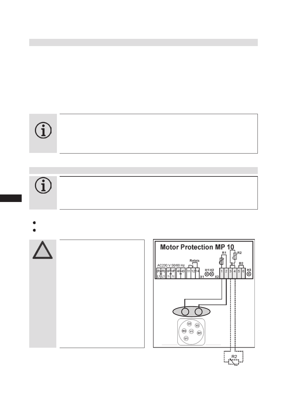
5.5 Connecting the trigger unit MP 10
Temperature monitoring connections:
Motor winding:
Terminals 1 - 2
Hot-gas side:
Terminals 3 - 4
ATTENTION!
Terminals 1 - 6 on the trigger
unit MP 10 and terminals PTC
1 and PTC 2 on the compres-
sor terminal board must not
come into contact with mains
voltage. This would destroy the
trigger unit and PTC sensors.
The supply voltage at L1-N
(+/- for DC 24 V version) must
be identical to the voltage at
terminals 11, 12, 14 and 43.