Carson SC-550-10 User Manual
Page 5
SC-550-10 Installation and Operating Instructions Page 5 of 12
CP4818B 6/30/04
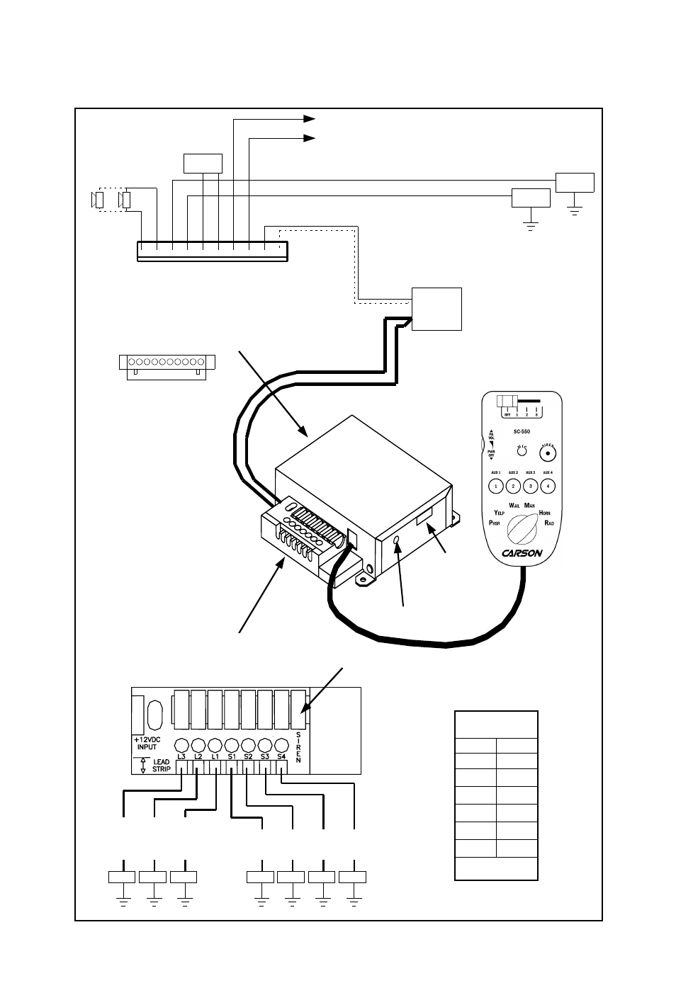
ELECTRICAL CONNECTIONS
(2) #18 AWG
(#16 - 2 SPKR)
2-SPKR - Connect for
same phase (+ to +)
S
P
KR
→
S
P
KR
→
OU
T
2
→
OU
T
1
→
R
AD
→
R
AD
→
AUX
→
CU
T
→
NEG
→
NEG
→
• • • • • • • • • •
Auxiliary Siren Input #22 AWG (See next page)
Cutout Input #22 AWG (See next page)
(2) #22 AWG
Connect to output
jack, terminals or
speaker of radio
#14 AWG
Use second lead
for 2 - SPKR
RADIO
Positive Supply
Use both terminals
#6 AWG Max. Wire Size
Each Terminal
(140A Max. Input Current)
(Not including siren amp)
-
BAT
+
CP4833-10 10-PIN CONNECTOR
Slide Switch Non-Progressive Output 1 #22 AWG (500mA Max.)
Slide Switch Non-Progressive Output 2 #22 AWG (500mA Max.)
RELAY
RELAY
LIGHT CONTROL OUTPUTS
20A Fuse for Siren Amp
LOAD LOAD LOAD
LOAD
Each Light Output Protected with 25A Fuse
Slide Switch
Progressive Outputs
(20A Max. per Output)
LOAD LOAD LOAD
Auxiliary Outputs
(20A Max. per Output)
Recommended
Wire Size
Amps
Size
5 - 10
#16
10 - 15
#14
15 - 25
#12
25 - 40
#10
40 - 60
#8
60 - 80
#6
Use next larger size
if longer than 10 ft.
Radio
Volume
Screw terminals face down.
Locking screws on side hold
connector to amp box.
Wiring not supplied.
DIP
Switch