Checkline LS-5-LED User Manual
Page 6
– 6 –
5.0 Connection
The stationary stroboscope has three connection sockets on the reverse of the unit which
share some identical functions and therefore offer a high level of lexibility. The possible
uses and labelling of these sockets are as follows:
Marking: 1
Use: Trigger signal input, connection of voltage supply.
Marking: 2
Use: Trigger signal input, connection of voltage supply.
Marking: Output
Use: Output of a trigger signal that is input into 1 or 2, connection of voltage supply.
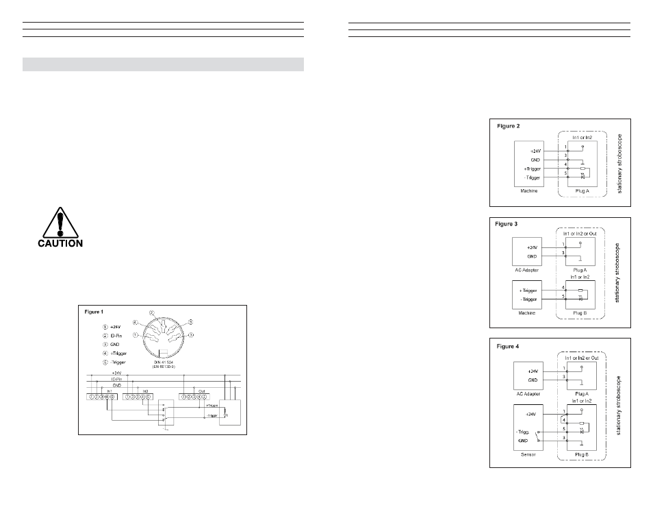
The assignment of plug contacts is shown in Fig 1 below..
• Please make the connections in accordance with the wiring diagram
(Fig. 1). The trigger input is potential-free. The potential-free input
is suitable for PNP and NPN signals. A matching plug for these input
sockets is included with the LS-5-LED.
• Do not trigger the LS-5-LED with signals above 120,000 FPM.
RECOMMENDATION!
Use a shielded cable to connect the trigger signal.
–7 –
5.1 Typical connection examples:
Please take connection examples from Figures 2 to 5. Please note that you will need
optional accessories for some of the examples (stroboscope control unit, AC Adapter,
sensor).
A. Trigger signal and supply voltage
from external equipment (Fig. 2).
B. Trigger signal from external
equipment (Fig. 3), supply
voltage from optional AC Adapter.
C. Trigger signal from optional
sensor (Fig. 4), supply voltage
for unit and sensor from optional
AC Adapter.