AJH Synth MiniMod Glide & Noise User Manual
Page 4
Copyright © AJHSynth 2014
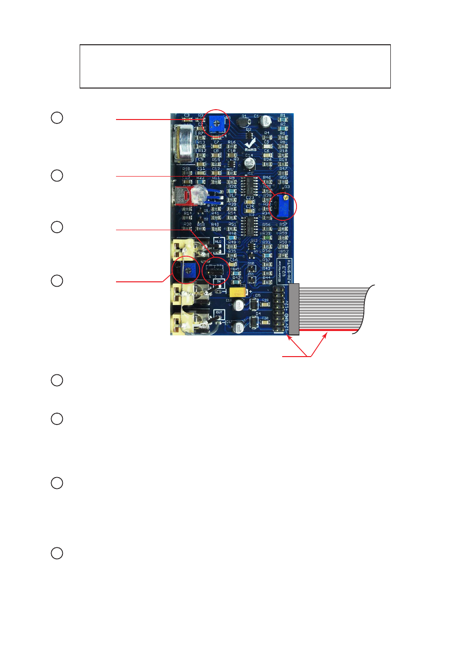
A Noise level :
Sets the output level of the White, Pink and Red Noise. This should be set to +/- 5 Volts
peak to peak, however higher or lower levels can be set if desired by adjusting this
trimmer.
B Glide Scale :
Sets the scaling of the Glide Output, it should be adjusted so that the Output tracks at
exactly 1 Volt per Octave. Note that there is a very slight offset between the Glide Input
and the Glide Output voltage, with the output being of the order of 10 to 25mv lower
than the Input. This is a function of the glide circuit design and can easily be compen-
sated for by adjusting the fine tune of any VCO’s which are connected to the Glide CV
Output.
C Hold Source (J1) :
J1 selects the Hold Source voltage that is normalised to the Hold CV Input if no patch lead is
connected to that Input.
Jumper connected to 1 & 2: Glide effect on at all times
Jumper connected to 2 & 3: Glide / Hold controlled by Gate CV signals on the Eurorack Bus
Jumper removed: Hold effect on at all times, Glide inactive and Output voltage held.
D Hold offset:
FOR MANUFACTURER ADJUSTMENT ONLY. Specialist test equipment is needed to
calibrate this trimmer correctly.
Note:
This information is given for completeness, the MiniMod Glide + Noise module is calibrated
after manufacture and under normal circumstances should not require any user adjustment.
Adjustment and Calibration
B Glide Scale
C Hold Source
D Hold Offset
A Noise Level
If you need any help using this module or have any technical questions please feel free to
contact us at [email protected]
Power Cable
Red Stripe aligns with -12V as shown