Fig. 1 - an illustration of minimod envelopes – AJH Synth MiniMod Dual Contour User Manual
Page 3
8 EG 2 Decay :
Sets the speed of the decay cycle for EG 2, and can be varied from 10 milliseconds to 10
seconds. The decay cycle commences either when the attack reaches it’s maximum level
or the gate pulse ends, whichever happens sooner.
9 EG 1 Sustain :
Sets the sustain level, between 0 to 8 volts for EG 1. It is only active when the gate is high,
as soon as the gate goes low the decay cycle recommences.
10 EG 2 Sustain :
Sets the sustain level, between 0 to 8 volts for EG 2. It is only active when the gate is high,
as soon as the gate goes low the decay cycle recommences.
13 EG 1 Status LED :
Gives a visual indication of the output level of Envelope Generator 1
11 EG 1 Decay Switch : With switch down the decay function is active on EG 1, when the switch is up the decay is
instantanious. This mimics the action of the Model D decay switch but we have added an
individual switch for each envelope rather than one switch which acts on both both.
12 EG 2 Decay Switch : With switch down the decay function is active on EG 2, when the switch is up the decay is
instantanious.
14 EG 2 Status LED :
Gives a visual indication of the output level of Envelope Generator 2
15 EG 1 Output :
This is the output from EG 1, and is typically between 0 and 8 volts, however with multiple
retriggering the output can go as high as 11 volts. This is not a problem to the CV inputs
of the MiniMod VCF and the MiniMod VCA which can safely handle these signal levels,
however caution is advised when connecting to Eurorack modules from other manufac-
turers.
We have included jumpers on the pcb (J1 and J2) which when removed lower the
nominal output voltage from 8 volts to 5.5 volts and limit the peak signal to 8 volts.
Please note that this jumper should be removed if using with other modules unless you
are certain that the higher CV voltages can be safely accommodated.
16 EG 2 Output :
This is the output from EG 2, and the signal levels are identical to EG 1 (see above)
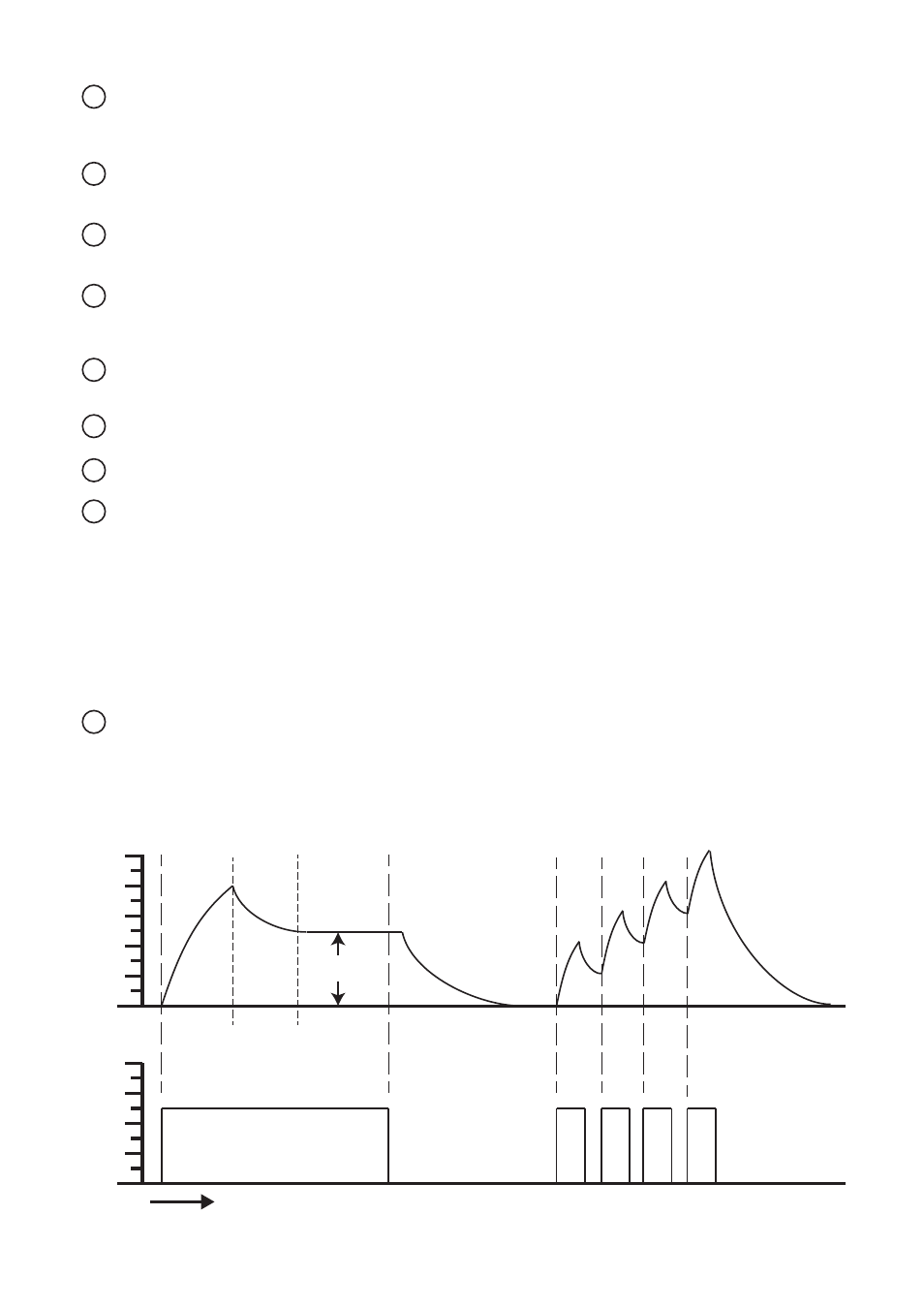
Sustain Level
0 to 8 Volts
Attack Phase
Decay 1
Decay 2
Always the same
rate as Decay 1
Sustain
0v
2v
4v
6v
8v
10v
0v
2v
4v
6v
8v
Gate On
On
On
On
On
Gate Off
Time
Fig. 1 - An Illustration of MiniMod Envelopes
Single Trigger
Fast Multiple Retrigger
O
utput L
ev
el
G
at
e Signal