Dynon Avionics SV-INTERCOM-2S User Manual
Page 13
Installation
SV-INTERCOM-2S Installation and User Guide - Revision A
2-5
shield (which is also grounded at pin 1) at the intercom end of the harness is a suitable way to
accomplish this goal.
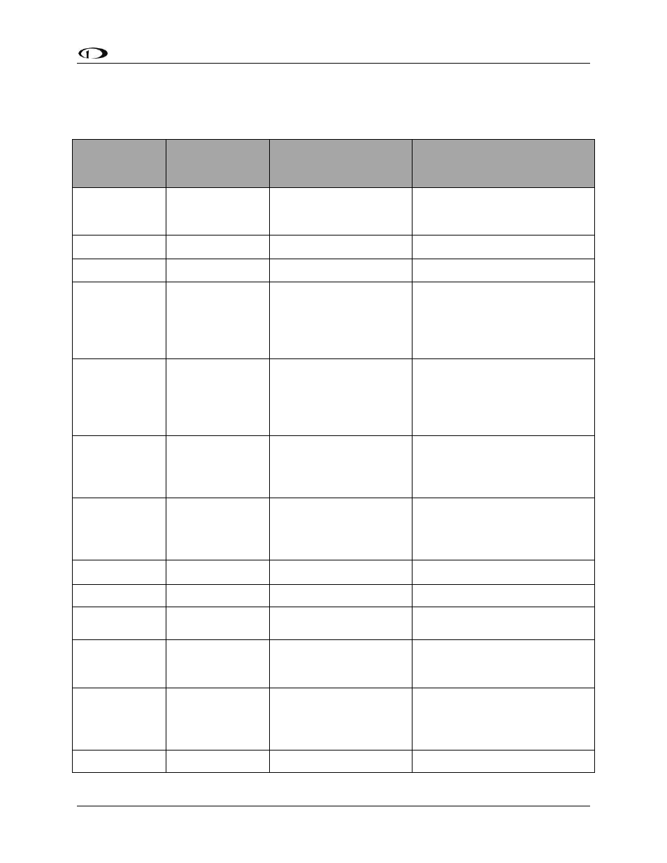
SV-INTERCOM-
2S
Pin
SkyView Unit
Pin
SV-INTERCOM-2S
Function
Notes
1
N/A
Master Ground In /
Master Shield Ground.
The shields of all shielded audio
cables should be connected to
this pin.
2
N/A
Microphone / PTT Ground
Pilot and Copilot
3
N/A
Copilot Microphone
4
N/A
Auxiliary Mono Muting
Input
This audio signal mutes when
audio signals are received on
other non-muting inputs and
radio inputs. Use this input for
NON critical audio signals.
5
SV-D700 / SV-
D1000(s)
D37 Pin 26
LED Dimmer Input
Used for SkyView Dimming
Output
If more than one SkyView display,
connect this to only ONE of the
SkyView displays. See note below.
6
SV-D700 / SV-
D1000(s)
D37 Pin 31
Stereo Non-Muting
(SkyView/EFIS) Audio
Input Right
This audio signal does not mute,
and is typically used to receive
audio from SkyView or other EFIS
system with stereo output.
7
SV-COM 425 #2
Pin 10
Radio 2 or Other Aux
Non-Muting Audio Input
This audio signal does not mute.
Typically used for a second COM,
a NAV radio, or other mono
avionics alerts.
8
N/A
Copilot Headphones Left
9
N/A
Pilot Headphones Left
10
N/A
Pilot Push-To-Talk Switch
Input
11
N/A
Stereo Music In Right
This input is over-ridden by the
Music In jack on the SV-
INTERCOM-2S
12
SV-COM-425 #1
Pin 5
SV-COM-425#2
Pin 5
Push-To-Talk Output
If two radios are used, this signal
must be switched between the
two radios so that only ONE radio
transmits at a time.
13
N/A
Power In