Shock assembly filling the shocks with oil, Assembly of the differential gear, Assembly of the bevel gear – OFNA Racing Worlds II User Manual
Page 5: Assembly of the spring
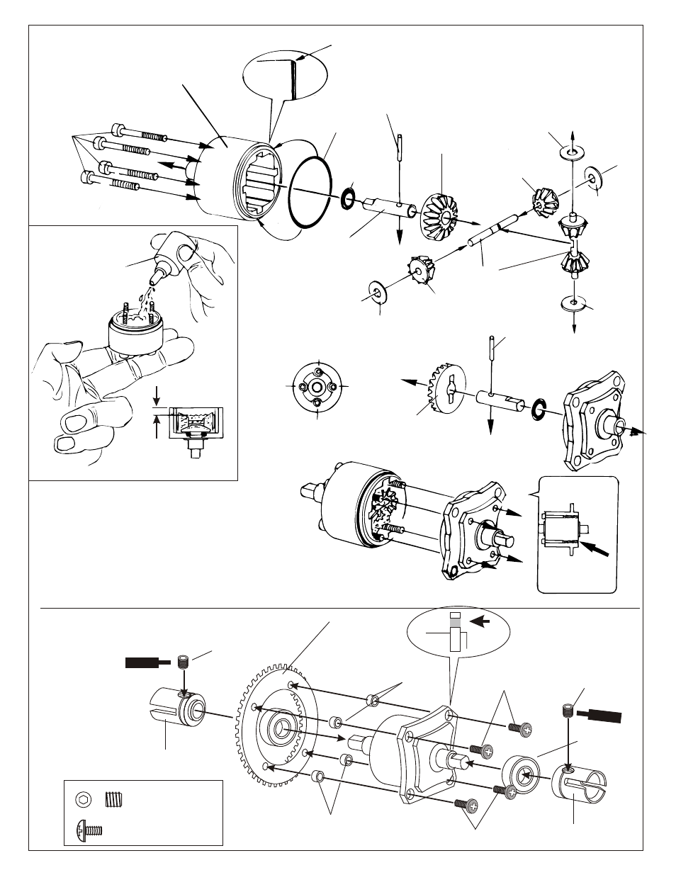
ASSEMBLY OF THE DIFFERENTIAL GEAR
#31322
Diff. Case ( Front/Rear )
#31323
Diff. Case (Center )
3 x 30mm
Cap Screw
#30779
O-Ring
#30779
0.5 x 26mm
O-Ring
#30779
2 x 12.8mm
Pin
#30779
2 x 12.8mm
Pin
#30771
Diff. Shaft
#30779
4 x 10mm
Washer
#30772
3.5mm
Cross Pin
#30770
Diff. Bevel Gear, Set
Grease
or
Silicone Oil
* Follow the number to tighten up
the screw.
* Tighten the Diff. Screws
to the end of the case
with 1 or 2 threads
* Position the O-ring as shown.
* Fill diff. Case with grease
during assembly.
ASSEMBLY OF THE BEVEL GEAR
#90026
5 x 5mm
Set Screw
#30120
Bevel Gear, 44T
Option:
#31010
HD Steel Bevel Gear, 44T
3mm
Tube
3mm
Tube
#30121
Mounting Hardware
3 x 5mm Screw & tube
3 x 5mm
Screw
#30082
Cap Joint, Long
( Build two differentials for front and rear. )
1
2
3
4
* Notice the diff case with the
straight holes are for front & rear.
5 x 5mm Set Screw
3 x 5mm Screw
* Push 3mm tubes into
holes of the diff. Case.
Screw
Cement
Screw
Cement
* Fill the diff. Case to approx 80% with
grease.
Building Notes:
• Set gear mesh in differential by tightening all four screws
until diff locks. Then loosen each screw ¼ turn. Diff should
still be hard to turn, but will smooth out after running.
If diff is too loose, the internal gears will quickly ware out
• When tightening the four screws, look for one thread
coming out of diff cover.
#30082
Cap Joint, Long
#30750
Diff Case, Bevel Gear
#30322
Diff Case, front / rear Complete
#90026
5 x 5mm
Set Screw
#30770
Diff. Bevel Gear, Set
#30770
Diff. Bevel Gear, Set
#30779
4 x 10mm
Washer
#30779
4 x 10mm
Washer
#30779
4 x 10mm
Washer
#30770
Diff. Bevel Gear, Set
Optional Silicone Oil:
#10231 - 1,000 wtg
#10232 - 3,000 wtg
#10233 - 5,000 wtg
#10234 - 7,000 wtg
#10235 - 10,000 wtg
#10236 - 30,000 wtg
#10237 - 50,000 wtg
#32237
O-Ring, rebuild
Shock Cylinder
( Make 2 for rear. )
( Make 2 for front.)
OIL
2. Pull down piston, attach pressure top
and shock oil overflow with tissue
paper.
SHOCK ASSEMBLY
FILLING THE SHOCKS WITH OIL
ASSEMBLY OF THE SPRING
1. Pull down piston and pour oil into
shock cylinder. Remove air bubbles
by slowly moving piston up and down.
3. Tighten up shock cap.
*Pull down.
*Move Slowly.
*Leave 3mm.
*Push Onto Shock
Cylinder
Shock Shaft
Piston
* Be careful not to damage shock shaft.
Pressure Top
#32044
Shock Cap, Hard Coated
*
Fit into groove.
#32203
Dust Pusher
(Yellow Rubber)
Oil Seal
* Fit into groove.
2mm
Washer
1mm
Washer
7mm
E-Ring
* E-Ring must
fit into groove as shown.
* Short shaft for front.
#32051
6mm Ball End,
Plastic parts bag
* Long shaft for rear.
2.6mm Nut
* Push 6mm ball joint
into ball end.
2.6 x 5mm
Washer
Spring Collar
Optional:
#32330
Red Spring set
#32340
Yellow Spring Set
Spring Holder
*Slide spring collar into Shock.
5mm
3mm
1mm
*Spring Tension adjust .
er
¼
u
Â
®
6mm
Ball Joint
#37380
* Screw down cap.
# 32033
* Assembly 4 pieces of the
shock Shaft .
#32291
Front, Short(w-gt) Shaft, 3.2mm
#32236
Rear, Long Shaft, 3.2mm
E-Ring
Hard Coated Shocks:
Front Super Shock, 3.2mm
# 32290
Rear Super Shock, 3.2mm
# 32230
#32051
6mm Ball End,
Plastic parts bag
Option:
#32039
O-ring Pistons
#32204
Spring Spacer Clips Set
#32051
All Plastic shock
parts bag
#30620
7 x 19x 5mm
Ballbearings
#30620
7 x 19x 5mm
Ballbearings