Assembly instructions 2/5, Step 1 – Home Styles 5543-13 User Manual
Page 3
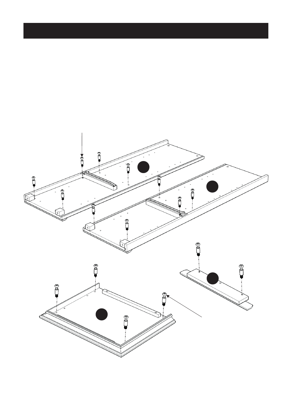
STEP 1
Assembly Instructions 2/5
A
Insert Cam Lock Screws into the pre-drilled holes of Top (A),
Base (E), Plinth (H).
Side Panel (B) and (C),
IMPORTANT
* Do not tighten up all the screws until each part is properly assembled.
* After assembly, item must be level to work properly. Use the included adjustable levelers to level.
* Use a soft cloth between these parts and the floor.
B
C
H
Cam Lock Screw
Cam Lock Screw