Allen&Heath GL2 User Manual
Allen&Heath Control panel
L2SM2
ALLEN & HEATH
11
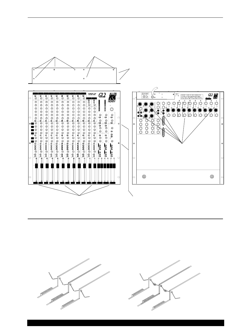
REPLACING A CHANNEL ASSEMBLY
If it is necessary to remove a channel assembly for service or replacement proceed as follows: Pull off the associated knobs.
Remove the potentiometer nuts using an 11mm nutdriver. Avoid scratching the control panel. Remove the ribbon cable
harness. Cut the solid wire earth busbar either side of the channel to be removed as shown below. Remove the associated fader
or desolder the fader wires as required.
When replacing the assembly make sure that the potentiometers, switches and LED indicators are correctly aligned with the
slots in the control panel. Check also the correct assignment of the Group and Stereo assemblies. Reconnect the earth busbar
by overlapping the wire where cut and soldering together. Use sufficient solder to ensure good joints.
ñ
CUT EACH
SIDE AT BEND
OVERLAP
AND SOLDER
ò
REMOVE 4x FRONT PANEL
M3 SCREWS
REMOVE ALL THE JACK NUTS
(15mm NUTDRIVER) AND 4AB
CONNECTOR SCREWS (XLRs,
PHONOS) AND D-CONNECTOR
NUTS IF FITTED.
REMOVE 2x POWER
UNIT SIDE M3
SCREWS.
DISCONNECT THE MAINS INPUT,
UNPLUG ALL CABLES AND REMOVE
THE CONSOLE FROM THE RACK OR
CASE.
INVERT THE CONSOLE
AND REMOVE 4x M3
BASE SECURING
SCREWS.
REMOVE 4x FRONT PANEL
SIDE M3 SCREWS AND NUTS
Œ
Œ
Œ
Œ
Œ
•
•
•
•
•
Ž
Ž
Ž
Ž
Ž
•
•
•
•
•
•
•
•
•
•
‘
‘
‘
‘
‘
DO NOT REMOVE
THESE 3x POWER
UNIT FIXING
SCREWS.
REMOVING THE BASE
Access to the internal assemblies of the GL2 and GL2-S is by removal of the chassis base from the front panel assembly. The
procedure detailed below also applies to the GL2-S. Only the power unit may be removed with the base in place: see section
REMOVING THE POWER UNIT
. Proceed in the sequence as follows:
CAREFULLY LIFT OFF
THE BASE.
’
’
’
’
’