Wine-Mate SSRWC Series User Manual
Page 21
- 20 -
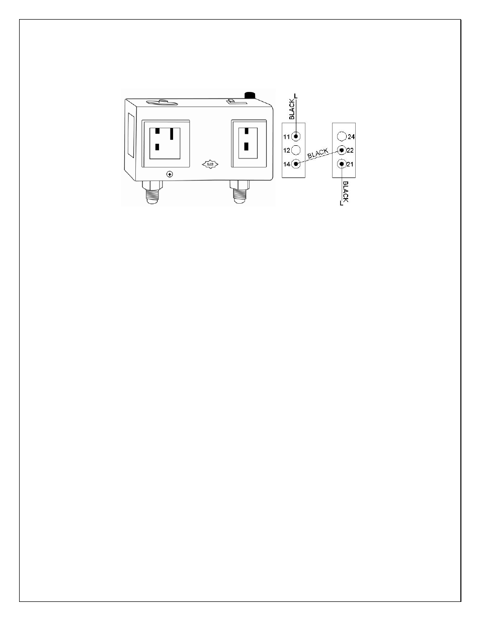
Head pressure setting: Cut out=230 psig; Cut in=150 psig; Differential=80 psig
It may need to adjust the setting in the field to get the right cycle time.
Fig. 10 Adjustable Pressure Control
6. Refrigeration Piping and Leak Testing
NOTES:
• The line connection sizes of liquid filter & indicator, the valve
connection sizes of condensing unit and the line connection sizes of
evaporator unit are not necessary the same as the listed refrigeration
line sizes.
• If the condensing unit is installed above the evaporator unit, use the
suction line one listed size smaller.
• Expansion and solenoid valves have been installed on the liquid line.
1) The installation order starts from condensing unit (including receiver and
discharge valve), liquid line filter-drier, moisture-liquid indicator, liquid line, to
evaporator unit (including liquid line connection, solenoid valve, expansion
valve, and suction line connection), returning to insulated suction line, suction
valve and then back to condensing unit.
2) If the condensing unit is located below the evaporator unit, use inverted U
trap to prevent liquid from flooding back to the compressor; if the elevation
difference is more than 10 ft or the line set exceeds 75 ft, use both inverted U
trap and suction accumulator.
3) If the condensing unit is located more than 10 ft above the evaporator unit,
use U trap to aid oil returning to the compressor.
4) Complete pipe brazing, check solenoid valve and expansion valve restrictions
and test leak.
5) Hook up the drain line and check if water drains.
6) Hook up the drain line and check if water drains.
The line sizes and refrigerant charges are listed as follows.