Installing and operating instructions – Wine-Mate SSW Series Digital Control Manual User Manual
Page 2
Installing and Operating Instructions
Vinotemp
2/3
5.2 HOW TO SEE THE MAX TEMPERATURE
1.
Press and release the o key.
2.
The “Hi” message will be displayed followed by the maximum temperature recorded.
3.
By pressing the o key again or by waiting 5s the normal display will be restored.
5.3 HOW TO RESET THE MAX AND MIN TEMPERATURE RECORDED
1. Hold press the SET key for more than 3s, while the max. or min temperature is displayed.
(rSt message will be displayed)
2. To confirm the operation the “rSt” message starts blinking and the normal temperature will
be displayed.
6. MAIN FUNCTIONS
6.1 HOW TO SEE THE SETPOINT
1. Push and immediately release the SET key: the display will show
the Set point value;
2. Push and immediately release the SET key or wait for 5 seconds to
display the probe value again.
6.2 HOW TO CHANGE THE SETPOINT
1. Push the SET key for more than 3 seconds to change the Set point value;
2. The value of the set point will be displayed and the “°C” or “°F” LED starts blinking;
3. To change the Set value push the o
or n arrows within 10s.
4. To memorise the new set point value push the SET key again or wait 10s.
6.3 HOW TO START A MANUAL DEFROST
Push the DEF key for more than 2 seconds and a manual defrost will
start.
6.4 HOW TO CHANGE A PARAMETER VALUE
To change the parameter’s value operate as follows:
1. Enter the Programming mode by pressing the Set + n keys for 3sec (the “°C” or “°F” LED
starts blinking).
2. Select the required parameter. Press the “SET” key to display its value
3. Use “UP” or “DOWN” to change its value.
4. Press “SET” to store the new value and move to the following parameter.
To exit: Press SET + UP or wait 15sec without pressing a key.
NOTE: the set value is stored even when the procedure is exited by waiting the time-out to
expire.
6.5 THE HIDDEN MENU (PR2)
The hidden menu Includes all the enabled parameters of the instrument.
6.5.1 HOW TO ENTER THE HIDDEN MENU
1. Enter the Programming mode by pressing the Set + n keys for 3 sec. (the “°C” or “°F” LED
starts blinking).
2. Released the keys, then push again the Set +n keys for more than 7sec. The Pr2 label will
be displayed immediately followed from the HY parameter.
NOW YOU ARE IN THE HIDDEN MENU.
3. Select the required parameter.
4. Press the “SET” key to display its value
5. Use o
or n to change its value.
6. Press “SET” to store the new value and move to the following parameter.
To exit: Press SET + o
or wait 15sec without pressing a key.
NOTE1: if no parameters are present in Pr1, after 3sec the “noP” message is displayed. Keep
the keys pushed till the Pr2 message is displayed.
NOTE2: the set value is stored even when the procedure is exited by waiting the time-out to
expire.
6.5.2 HOW TO MOVE A PARAMETER FROM THE HIDDEN MENU TO THE
FIRST LEVEL AND VICEVERSA.
Each parameter present in the HIDDEN MENU can be removed or put into “THE FIRST LEVEL”
(user level) by pressing “SET + n”.
In HIDDEN MENU when a parameter is present in First Level the decimal point is on.
6.6 HOW TO LOCK THE KEYBOARD
1.
Keep pressed for more than 3 sec the UP + DOWN keys.
2.
The “POF” message will be displayed and the keyboard will be locked. At this point it will be
possible only to see the set point or the MAX or Min temperature stored
3.
If a key is pressed more than 3s the “POF” message will be displayed.
6.7 TO UNLOCK THE KEYBOARD
Keep pressed together for more than 3s the o
and n keys, till the “Pon” message will be
displayed.
7. PARAMETERS
REGULATION
Hy Differential: (0,1 ÷ 25,5°C / 1÷255 °F) Intervention differential for set point. Compressor Cut
IN is Set Point + differential (Hy). Compressor Cut OUT is when the temperature reaches
the set point.
LS Minimum set point: (- 50°C÷SET/-58°F÷SET): Sets the minimum value for the set point.
US Maximum set point: (SET÷110°C/ SET÷230°F). Set the maximum value for set point.
Ot Thermostat probe calibration: (-12.0÷12.0°C; -120÷120°F) allows to adjust possible offset
of the thermostat probe.
COn Compressor ON time with faulty probe: (0÷255 min) time during which the compressor is
active in case of faulty thermostat probe. With COn=0 compressor is always OFF.
COF Compressor OFF time with faulty probe: (0÷255 min) time during which the compressor
is OFF in case of faulty thermostat probe. With COF=0 compressor is always active.
DISPLAY
CF Temperature measurement unit: °C=Celsius; °F=Fahrenheit. WARNING: When the
measurement unit is changed the SET point and the values of the parameters Hy, LS, US,
Ot, ALU and ALL have to be checked and modified if necessary).
rES Resolution (for °C): (in = 1°C; dE = 0.1 °C) allows decimal point display.
dLy Display delay: (0 ÷20.0m; res.10sec) when the temperature increases, the display is
updated of 1 °C/1°F after this time.
DEFROST
IdF Interval between defrost cycles: (0÷120h) Determines the time interval between the
beginning of two defrost cycles.
MdF (Maximum) length for defrost: (0÷255min) When P2P = n, (not evaporator probe: timed
defrost) it sets the defrost duration, when P2P = y (defrost end based on temperature) it
sets the maximum length for defrost.
dFd Temperature displayed during defrost: (rt = real temperature; it = temperature at defrost
start; SEt = set point; dEF = “dEF” label)
dAd MAX display delay after defrost: (0÷255min). Sets the maximum time between the end of
defrost and the restarting of the real room temperature display.
FANS
FnC Fans operating mode: C-n= runs with the compressor, OFF during defrost;
o-n = continuous mode, OFF during defrost;
C-Y = runs with the compressor, ON during defrost;
o-Y = continuous mode, ON during defrost;
Fon Fan ON time: (0÷15 min) with Fnc = C_n or C_y, (fan activated in parallel with
compressor). it sets the evaporator fan ON cycling time when the compressor is off. With
Fon =0 and FoF ≠ 0 the fan are always off, with Fon=0 and FoF =0 the fan are always off.
FoF Fan OFF time: (0÷15 min) with Fnc = C_n or C_y, (fan activated in parallel with
compressor). it sets the evaporator fan off cycling time when the compressor is off. With Fon
=0 and FoF ≠ 0 the fan are always off, with Fon=0 and FoF =0 the fan are always off.
ALARMS
ALC Temperature alarms configuration: (Ab; rE)
Ab= absolute temperature: alarm temperature is given by the ALL or ALU values. rE =
temperature alarms are referred to the set point. Temperature alarm is enabled when the
temperature exceeds the “SET+ALU” or “SET-ALL” values.
ALU MAXIMUM temperature alarm: (SET÷110°C; SET÷230°F) when this temperature is
reached the alarm is enabled, after the “ALd” delay time.
ALL Minimum temperature alarm: (-50.0 ÷ SET°C; -58÷230°F when this temperature is
reached the alarm is enabled, after the “ALd” delay time.
AFH Differential for temperature alarm recovery: (0,1÷25,5°C; 1÷45°F) Intervention
differential for recovery of temperature alarm.
ALd Temperature alarm delay: (0÷255 min) time interval between the detection of an alarm
condition and alarm signalling.
OTHER
Adr Serial address (1÷244): Identifies the instrument address when connected to a ModBUS
compatible monitoring system.
dP1 Thermostat probe display
rSE Real set point: (readable only), it shows the set point used during the energy saving cycle
or during the continuous cycle.
rEL Software release for internal use.
Ptb Parameter table code: readable only.
8. TTL SERIAL LINE – FOR MONITORING SYSTEMS
The TTL serial line, available through the HOT KEY connector, allows by means of the external
converter, to connect the instrument to a monitoring system
.
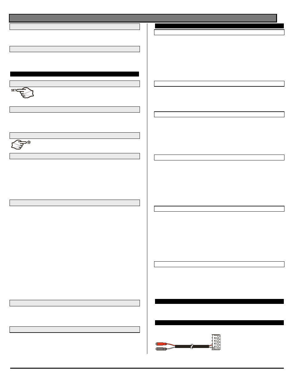
9. X-REP OUTPUT – OPTIONAL
As optional, an X-REP can be connected to the instrument, trough the HOY KEY connector.
The X-REP output EXCLUDES the serial connection.
To connect the X-REP to the instrument
the following connectors must be used
CAB-51F(1m), CAB-52F(2m), CAB-
55F(5m),