Wine guardian, Humidifier “quick start” installation guide – Wine Guardian Humidifier - Quick Start User Manual
Page 2
Wine Guardian
®
Humidifier
Integrated and Freestanding
Quick Start
Installation Guide
This document is a pictorial guide on installing the Wine Guardian hu-
midifier system. It is not intended to replace the detailed instructions
found in the WG Humidifier Installation, Operation and Maintenance
(IOM) manual, which includes important safety messages all WG in-
stallers and owners should carefully follow for safe and optimal per-
formance of the system.
Refer to the IOM manual for installation instructions related to duct col-
lars and duct collar kits, optional remote interface control and remote
sensors.
Wine Guardian
®
Humidifier
“Quick Start” Installation Guide
6. Controller set-up instructions
A Locate the Wine Guardian remote
interface controller within the wine
cellar or proceed to the Wine Guard-
ian Through-the-Wall (TTW) main
control panel. (Fig. A & Fig. B)
B Press the mode button and hold it
down for five (5) seconds. The screen
will advance to the set up menu and
“1 F” or “Setting # 1” will appear on
the screen. (Fig. C & Fig. D)
C Continue to press the mode button to
advance to setup screen “6 0” or
“Setting # 6”. (Fig. E & F)
D Press the up arrow to advance this
setting to either “1” for Integrated
Humidifier (mounted at Wine Guard-
ian or “2” for Freestanding Humidi-
fier Unit. (Fig. G & H)
E Controller setup is complete.
5. Installing Freestanding Humidi-
fier—with power cord and hu-
midistat
A. Follow Step 3 (TTW or within
racking) or Step 4 (surface mount),
A-H.
B. Plug power adapter into 120 volt/1
phase/60 hertz receptacle. (Fig. A)
C. Mount independent humidistat
within wine room mid-point on
wall or racking in an area that has
sufficient access. (Fig. B)
D. Refer to Humidistat Operations
Manual for additional information
E. Installation is complete.
Visit www.wineguardian.com/distributors
Or call 800-825-3268 or 315-452-7400
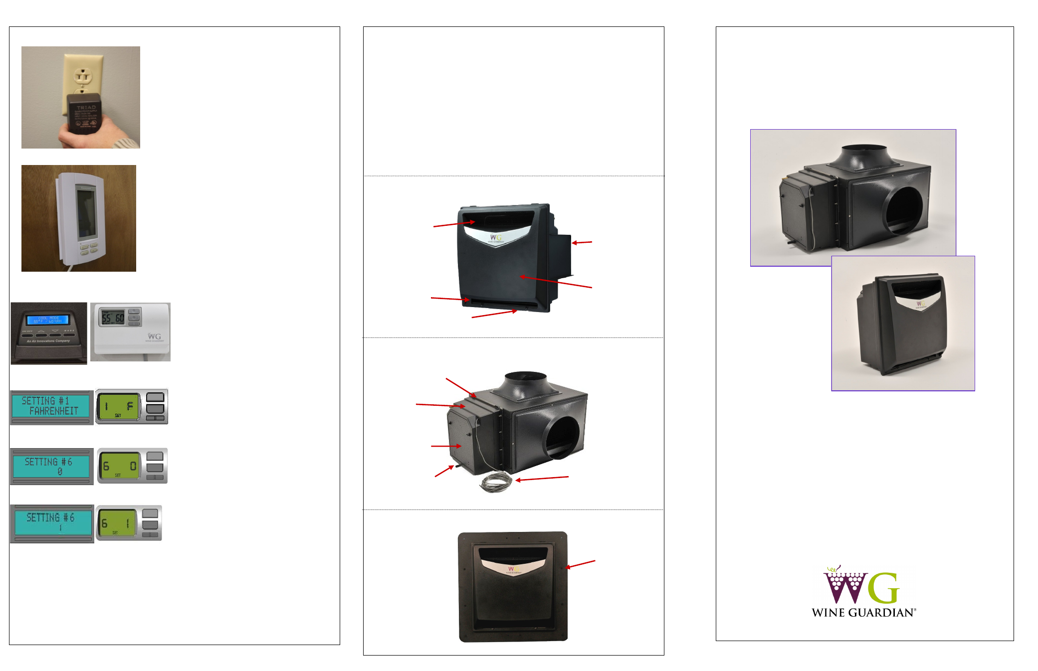
Fig. A (TTW) Fig. B (Ducted)
Fig. C (TTW) Fig D (Ducted)
Fig. E (TTW) Fig. F (Ducted)
Fig. G (TTW) Fig. H (Ducted)
Photos to come
Air intake
Air outlet
Wall mount
bracket
Front access
cover
Access cover
attachment screws
Fig. A
Fig. B
Front of Unit—Freestanding
Adapter plate
Humidifier
housing
Humidifier pad
Access cover
Drain connection
Power/control
cable
Back of Unit—Integrated
Mounting bracket
Through Wall Mount