WFCO WF-8725P User Manual
Page 6
2
IN
S
T
A
L
L
A
T
IO
N
IN
S
T
R
U
C
T
IO
N
S
OEM Installation of the WFCO WF-8712 and WF-8725
Power Center
Select a mounting location near the shore power and battery (batteries)
and cut a rough opening 1/8? wider than the box to allow the power
center to slide in easily.
Select a mounting location that is appropriate to prevent excessive
heat, water, moisture, dust and dirt entering the unit installed. Allow
a minimum of two cubic feet of clear airspace and any additional
venting as necessary to prevent the unit from overheating.
The fuse rating that the manufacturer suggests for the output fuses
will be marked on the unit. Replace only with same type and rating.
During the manufacturing process, be sure that all converter openings
are protected from debris falling into the unit. (This is a non-warranty
item.)
NOTE: If the reverse battery protection fuses are blown during
installation, be sure that the battery has been connected properly, then
replace the fuses with ATC “Littelfuse ” Type 257 with the same rating
as the original.
WARNING
!
!
CAUTION
!
!
®
This unit employs components that tend to produce arcs or sparks.
To prevent fire or explosion, do not install in compartments
containing batteries or flammable materials
To prevent fire, do not cover or obstruct ventilation openings.
Do not mount in zero-clearance compartment.
Overheating may result.
For continued protection against risk of fire, or electric shock
replace only with same type and ratings of fuse.
(LP gas).
TM
3
IN
S
T
A
L
L
A
T
IO
N
I
N
S
T
R
U
C
T
IO
N
S
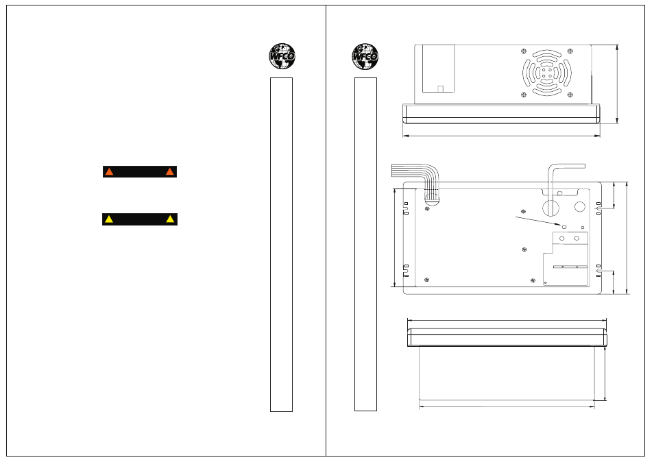
(Figure. 1)
11 15/16
?
5
1
/8
”
1
1
1
5
/1
6
”
4
1/
8
?
1
7/
8
?
2
1
/8
?
7
3/
16
?
1
0
7
/1
6
?
6
1/
16
?
GROUND WIRE HOLE
12
0V
A
C
I
N
DC OUTPUT
TM