WFCO WF-8740P User Manual
Page 6
3
IN
S
T
A
L
L
A
T
IO
N
I
N
S
T
R
U
C
T
IO
N
S
OEM Installation of the WFCO 8735/40 Power Center
(This is a non-warranty item.)
NOTE:
Select a mounting location near the shore power and battery (batteries)
and cut a rough opening 1/8 wider than the box to allow the power
?
center to slide in easily.
The fuse rating that the manufacturer suggests for the output fuses will
be marked on the unit. Replace only with same type and rating.
During the manufacturing process, be sure that all converter openings are
protected from debris falling into the unit.
If the reverse battery protection fuses are blown during
installation, be sure that the battery has been connected properly, then
replace the fuses with ATC "Littelfuse ” Type 257 with the same rating as
the original.
Select a mounting location that is appropriate to prevent excessive
heat, water, moisture, dust and dirt entering the unit installed. Allow
a minimum of two cubic feet of clear airspace and any additional
venting as necessary to prevent the unit from overheating.
WARNING
!
!
CAUTION
!
!
®
This unit employs components that tend to produce arcs or sparks.
To prevent fire or explosion, do not install in compartments
containing batteries or flammable materials (LPgas).
To prevent fire, do not cover or obstruct ventilation openings.
Do not mount in zero-clearance compartment.
Overheating may result.
For continued protection against risk of fire, or electric shock
replace only with same type and ratings of fuse.
TM
2
IN
S
T
A
L
L
A
T
IO
N
IN
S
T
R
U
C
T
IO
N
S
For proper wire sizes and torque requirements, refer to the label on the
door assembly.
(Figure. 2)
8.07
?
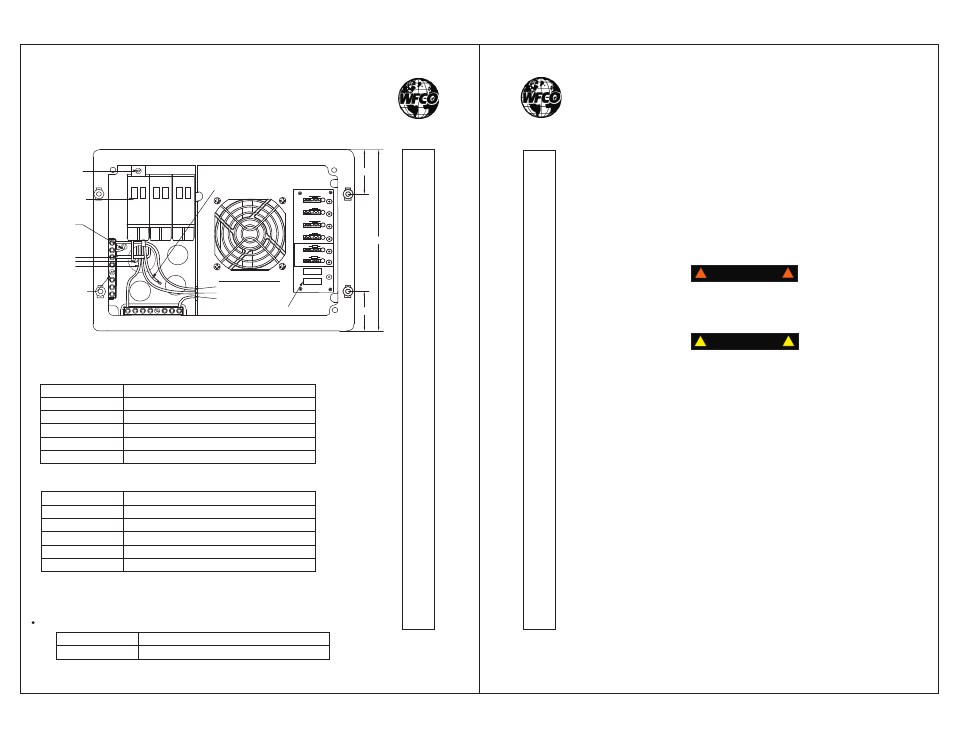
WF-8735 and WF-8740 Wiring Diagram
TM
1.77
?
1.97
?
AC NEUTRAL TERMINAL BAR
GREEN WIRE (Ground)
BLACK WIRE (Hot)
WHITE WIRE (Neutral)
AVAILABLE FOR
A BRANCH CIRCUIT
RE VE RS E BAT TE RY PR OT EC TI ON FUS E
FROM CONVERTER:
MAIN BREAKER
CHASSIS
GROUND
30A
MAIN BREAKER
HOLD DOWN
AC GROUND
TERMINAL BAR
SHORE POWER:
GROUND
HOT
NEUTRAL
FUSE
F1
R1
LED1
F2
R2
LED2
F3
R3
LED3
F4
R4
LED4
F5
R5
LED5
F6
R6
LED6
REVERSE BATTERY
PROTECTION FUSE
FUSE
UL-Listed Main Circuit Breakers, rated for 120 Vac, maximum 30 Aac
Breaker Filler Plates:
Manufacturer
Cutler Hammer
Thomas Betts
ITE/Siemens
Square D
Murray
Model/Cat. No./Type
Type BR and C
Type TB or TBBD
Type QP or QT
Type HOM or HOMT
Type MP-T or MH-T
Acceptable circuit breakers are as follows:
UL-Listed Branch Circuit Breakers, rated for 120 Vac, maximum 20 Aac
Manufacturer
Cutler Hammer
Thomas Betts
ITE/Siemens
Square D
Murray
Model/Cat. No./Type
Type BR and C, Type BRD BD and A
Type TB and TBBD
Type QP or QT
Type HOM and HOMT
Type MH-T or MP-T
Acceptable circuit breakers are as follows:
Manufacturer
WFCO
Model/Cat. No./Type
FP-01 or FP-01B
- A replacement or additional circuit breaker shall be of the same manufacturer,
type designation, and equal or greater interrupting rating, not to exceed 30 A.
- Short-Circuit-Current” rating for the breaker should be 10,000 A.
“
®
®