Carrier PERFORMANCETSERIES EDGER THERMIDISTATT CONTROL TP-PRH-A User Manual
Page 9
9
A07686
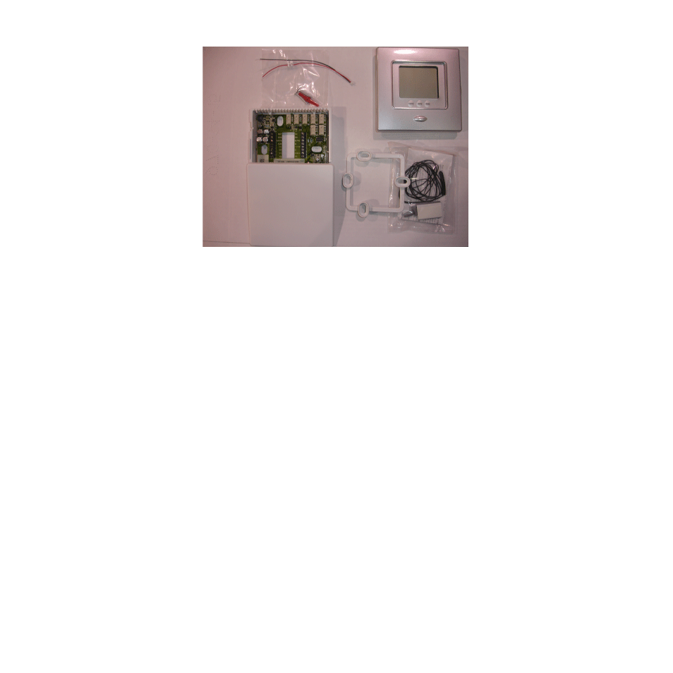
Fig. 3 − TP−NRH−A Carton Contents
1. Display Module
2. Stand−off for Equipment Control Module
3. Outside Air Temperature Sensor, screws and pigtail
4. Equipment Control Module
Thermidistat Control Location
Thermidistat Control should be mounted:
S
Approximately 5 ft (1.5m) from floor.
S
Close to or in a frequently used room, preferably on an inside
partitioning wall.
S
On a section of wall without pipes or duct work.
Thermidistat Control should NOT be mounted:
S
Close to a window, on an outside wall, or next to a door leading to the
outside.
This manual is related to the following products: