Special requirements for marine installations – Thetford EV54 Series User Manual
Page 4
A combination of a roof jack and lower vent or two side vents
offers adequate venting for high outside ambient temperatures.
The more air circulating over the condenser (located at rear), the
more efficient the refrigerator will operate. Failure to provide the
necessary ventilation will result in poor refrigeration. If operation
at low outside ambient temperatures is necessary (below 23° F)
all exterior venting must be covered to prevent serious perform-
ance loss.
When installation incorporates exterior venting and operation at
low outside ambient temperatures is necessary (below 23° F), ex-
terior venting must be covered or reduced cooling efficiency in
cabinet will result.
Power Supply
Provisions are made for connection of either 12 volts DC or 120
volts AC to the refrigerator. If both 12 volts DC and 120 volts AC
are simultaneously supplied, a special relay in the refrigerator
power supply allows the unit to run on 120 volts AC. To convert
to DC power, the AC supply is simply disconnected.
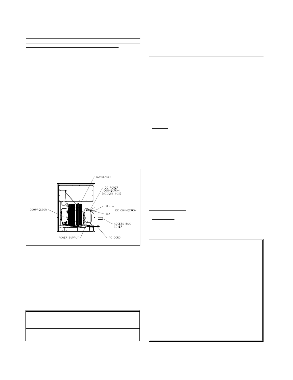
DC Power Connection
The DC supply connection is located behind the louvered ac-
cess panel at the bottom front of the unit. Remove the screw
from the top center of the access panel and remove the panel.
The DC terminal box is located in the control power supply as-
sembly (See Figure 3). The positive and negative DC supply con-
nections are located in this terminal box. The terminal box is pro-
vided with knock-out holes for routing the DC lead wires through
the side of the terminal box.
CAUTION: The DC lead wires must be protected from physical
damage to the insulation. Approved wire clamps
must be used at the knock-out hole according to
governing codes such as National Electric Code,
ART.555 or ABYC Section E9.15 or the specific local
code.
The size of the wire from your 12 volt DC battery is dependent
upon the distance between the refrigerator and the battery. Refer
to Table 2 for wire size.
Table 2
This recommended wire size is to prevent a voltage drop at the
refrigerator which is critical to DC performance.
Use of wire sizes smaller than those listed may cause excessive
DC running time, shorter battery life, and poor performance due
to line loss.
It is important that the 12 volt, DC supply wires be connected
directly to the battery and that the wires are dedicated to the
refrigerator (other appliances are connected by separate wires).
This practice minimizes the possibility of radio and T.V. interfer-
ence. Twisting the positive and negative supply wires further
helps to nullify the induction effects which could further add to
radio/T.V. interference.
To the leads located in the terminal box, connect the positive
battery lead to the red wire and the negative battery lead to the
black wire (important to be well insulated). These splices should
be soldered or connected by means of an approved splice con-
nector. Tape the spliced connections generously before replacing
the terminal cover box.
A 15 amp fuse should be installed as close to the battery as
possible in the positive wire leading to the refrigerator. This fuse
will protect the wiring from the battery to the refrigerator in the
event of a short circuit.
CAUTION: DO NOT OPERATE REFRIGERATOR ON BATTERY
ALONE. THE BATTERY MUST HAVE A CHARGING
MEANS SUCH AS AN ON-BOARD GENERATOR; IF
NOT, THE BATTERY WILL DISCHARGE IN A SHORT
PERIOD OF TIME.
Further information on DC supplies can be found later in this
manual.
AC Power Connection
The 120 volt AC power connection is made by connecting the
refrigerator’s AC cord to a standard 120 volt grounded receptacle.
See Figure 3.
The 120 volt AC supply wires, to which the refrigerator is con-
nected, should be routed through the fuse panel or circuit
breaker that protects the vehicle when an outside power source is
used. This connection should be permanently wired in accord-
ance with existing governing codes. The use of an extension cord
is not recommended.
IMPORTANT:
IF AC POWER IS SUPPLIED BY AN ON-BOARD GENERATOR,
IT IS VERY IMPORTANT TO HOLD BOTH VOLTAGE AND FRE-
QUENCY WITHIN THE TOLERANCES STATED IN THE FRONT
OF THIS MANUAL.
Special Requirements For
Marine Installations:
The DE-540 is internally wired so that the AC and DC cir-
cuits are isolated from each other. If the positive (+ 12 volts)
DC input is grounded in any way (cuts in the wire insulation,
improperly insulated connections, etc.), a voltage potential
could be developed throughout the boat in which corrosion
develops on any metal parts exposed to water.
This situation may be avoided by wiring the boat so that
AC and DC grounds are common and wiring is protected per
NNMA CERTIFICATION HANDBOOK (1987). Inspect all wiring
to insure that insulation has not been damaged. Plastic wire
clamps are recommended.
To obtain more information on corrosion, a good reference
is:
BOAT AND YACHT CORROSION CONTROL
by Yacht Corrosion Consultants, Inc.
2368 Eastman Ave. # 6, Ventura, Ca. 93003.
12 Volt Supply Wiring And Fuse Size
Min. Wire
Max. Fuse
Size
Size
0 -12’
14 AWG
15 AMP
12’ - 20’
12 AWG
15 AMP
over 20’
10 AWG
15 AMP
Figure 3
4