Decorative door panel installation, Reversing door swing – Thetford 6100 Series User Manual
Page 11
Within 20 seconds the flame will go out, indicating
the safety lock-out circuit is operational. Reconnect
the wire to the ignition module upon completion of
the test.
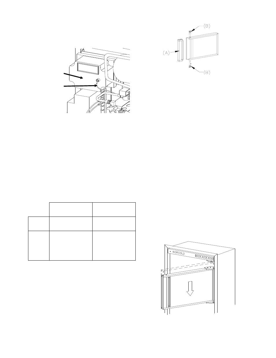
Door Panel Installation
The Norcold refrigerator doors provide slots for in-
serting decorative panels. Installation of the panels is
accomplished by removing the handle assembly, in-
serting the decorative panel, and re-inserting the
handle assembly. This procedure applies to both
doors. (See Figure 12)
The frame slots are designed to accept panel thick-
ness up to 3/16" maximum.
TABLE 4
PANEL DIMENSIONS
662, 663
6162, 6163
682, 683
6182, 6183
Upper
Door
19 11/16" x 16"
19 11/16" x 16"
Lower
Door
19 11/16" x 32 1/4"
19 11/16" x 39 1/4"
Note:
use this dimension
for models 652,3 &
6052,3 outer door
INSTRUCTIONS
1. Prepare panel by cutting to size indicated in ac-
companying chart. (See TABLE 4)
2. Remove handle assembly (A) by removing four
screws (B). (See Figure 12)
3. Slide panel into frame slots.
4. Replace the handle assembly.
Instructions for Reversing Door Swing
Your refrigerator is equipped with convertible hinges
which allows the door swing to be changed at any-
time.
TOOLS REQUIRED
Phillips Screwdriver - Size #2
Two Slotted Screwdrivers
REMOVING THE DOORS
1. Remove all items of food, juices, etc., from the
doors. Remove the juice rack and storage bins.
Close both doors before removing hinge pins.
2. Remove the top hinge pin using one of the slot-
ted screwdrivers. Remove the center hinge pin
(both pieces) using the two slotted screwdriv-
ers; one on each end of the pin. Lastly, remove
the bottom hinge pin. Be sure to save the pins
for reassembly later. (See Figure 19)
3. Remove the upper door by opening the door
slightly and pulling the bottom of the door away
from the refrigerator. Allow enough room to
slide the door down off of the upper hinge pin
shoulder. (See Figure 13)
Ignition Module
Electrode Wire
Figure 11
Figure 12
Figure 13
1
1