Ice maker wiring pictorial and diagram (optional) – Thetford 1210 Series AC - Through 04/06/09 User Manual
Page 18
Owner’s Manual 18
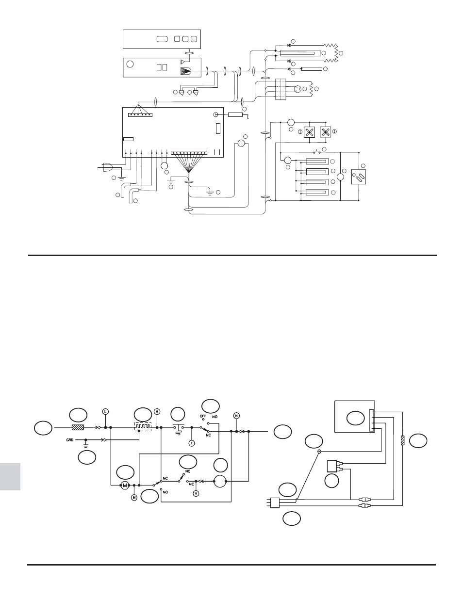
The parts of the ice maker wiring pictorial and diagram are (See Art01500):
1 ................................................................................................................................................................................ 120V AC Hot / smooth
2 ............................................................................................................................................................................ 120 VAC Neutral / ribbed
3 ............................................................................................................................................................................................. Ground screw
4 .............................................................................................................................................................................................. Thermal fuse
5 ................................................................................................................................................................................... Solenoid water valve
6 .................................................................................................................................................................................................... Ice maker
7 ................................................................................................................................................................................................. Mold heater
8 ................................................................................................................................................................................................. Thermostat
9 ............................................................................................................................................................................................ Shut off switch
10 .................................................................................................................................................................................................. Fill switch
11 ............................................................................................................................................................................................... Hold switch
12 ......................................................................................................................................................................................................... Motor
Ice Maker Wiring Pictorial and Diagram (Optional)
Art01770
5
L1
L2
P1
1
7
5
OVERLAY/REV˚TRMENT
DISPLAY BOARD/
CARTE D AFFICHAGE
POWER BOARD/ PANNEAU D ALIMENTATION
+12VDC/VCD
G
G
4
P2
T1
S
5 AMP
5 AMP
AC_HT_HI
LIMIT_IN
LIMIT_OUT
AC_HT_LO
AC_HT_HI
AC_HT_LO
GND
12VDC
T
B
B
A
11
T
8
-12VDC/VCD
H
7
M
L
K
J
N
R
P
Q
O
1
6
2
D
C
3
2
4
1
1
E
U
F
F
6
1
10
1
F
V
T
F2
F1
Art01500
109
110
111
114
115
N
G
L
44
GRN / VERT
BRN / BRUN
WHT / BLANC
BLK / NOIR
NEUTRAL (RIBBED) /
NEUTRE ( NERVURES)
WHT / BLANC
HOT(SMOOTH)/
CHAUD (PLAT)
GRN / VERT
109
112
116
120
119
96
118
44
117
110
111