Т³гж 7 – Pridiom Elite Series PWS247EL Installation Manual User Manual
Page 7
11
11
12
12
Air and moisture in the refrigerant system have undesirable effects as indicated below:
Pressure in the system rises.
Operating current rises.
Cooling or heating efficiency drops.
Moisture in the refrigerant circuit may freeze and block capillary tubing.
Water may lead to corrosion of parts in the refrigeration system.
Therefore, the indoor unit and tubing between the indoor and outdoor unit must be leak tested
and evacuated to remove any noncondensables and moisture from the system.
1.Air purging with vacuum pump
Preparation
Check that each tube(both liquid and gas side tubes) between the indoor and outdoor units
have been properly connected and all wiring for the test run has been completed. Remove
the service valve caps from both the gas and the liquid side on the outdoor unit. Note that
both the liquid and the gas side service valves on the outdoor unit are kept closed at this
stage.
Pipe length and refrigerant amount:
Air purging
Connective
pipe length
Less than 7.5m
More than 7.5m
Air purging
method
Use vacuum
pump.
Use vacuum
pump.
Additional amount of refrigerant to be charged
R22: (Pipe length-7.5)x30g/m
R410A: (Pipe length-7.5)x15g/m
Liquid side: 6.35
R22: (Pipe length-7.5)x60g/m
R410A: (Pipe length-7.5)x30g/m
Liquid side: 9.52
Bar
Copper pipe
Clamp handle
Red arrow mark
Cone
Yoke
Handle
Bar
"A
"
C: Putting nut on
Remove flare nuts attached to indoor and
outdoor unit, then put them on pipe/tube
having completed burr removal.(not possible
to put them on after flaring work)
Flare nut
Copper tube
Fig.14
Fig.15
D: Flaring work
Firmly hold copper pipe in a die in the
dimension shown in the table below.
Caution
Align the center of the pipes.
Sufficiently tighten the flare nut with fingers,
and then tighten it with a spanner and torque
wrench as shown in Fig.16 & 17.
2. Tightening Connection
Excessive torque can break nut depending on
installation conditions.
Indoor unit tubing
Flare nut
Pipings
Fig.16
Outer diam.
(mm)
A(mm)
Max.
Min.
6.35
1.3
0.7
9.52
1.6
1.0
12.7
1.8
1.0
12.7
16
1.8
2.2
1.0
2.0
Outer
diam.
Tightening
torque(N.cm)
Additional tightening
torque(N.cm)
6.35
12.7
16
9.52
1500
(153kgf.cm)
1600
(163kgf.cm)
3500
(357kgf.cm)
3600
(367kgf.cm)
2500
(255kgf.cm)
2600
(265kgf.cm)
4500
(459kgf.cm)
4700
(479kgf.cm)
B: Burr removal
1. Completely remove all burrs from the cut
cross section of pipe/tube.
2. Put the end of the copper tube/pipe in a
downward direction as you remove burrs in
order to avoid dropping burrs into the tubing.
Pipe
Reamer
Point down
Fig.13
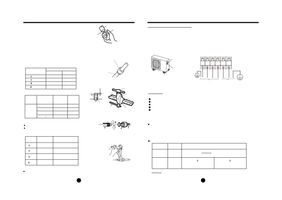
1. Remove the electrical control board cover from the outdoor unit by loosening the screw.
2. Connect the connective cables to the terminals as identified with their respective matched
numbers on the terminal block of indoor and outdoor units.
3. Secure the cable onto the control board with the cord clamp.
4. To prevent the ingress of water, form a loop of the connective cable as illustrated in the
installation diagram of indoor and outdoor units.
5. Insulate unused cords (conductors) with PVC-tape. Process them so they do not touch any
electrical or metal parts.
Cover
Screw
OUTDOOR UNIT INSTALLATION
OUTDOOR UNIT INSTALLATION
Connect the cable to the outdoor unit
Fig.17
Fig.18
Terminal block of outdoor unit
To indoor unit
To power supply
Model B
W L1 L2 S L 1 L2
NOTE:
Connective pipe length will affect the capacity and energy efficiency of the unit.
The nominal efficiency is tested basing on the pipe length of 7.5m.
E: Pipe length
Model
R410A
inverter
split air
condtioner
Max. Length
of refrigerant
pipe(m)
Max. drop
height
(m)
Capacity
(Btu/h)
25
10
30
20
50
65
25
30
<15000
>15000~<24000
>24000~<36000
>36000~<60000