Operation – Chicago Electric Model 55250 User Manual
Page 7
Page 7
SKU 55250
For technical questions, please call 1-800-444-3353.
Operation
Controls and Indicators
Welding
Caution: Before arc welding, read and understand all safety precautions and warnings
listed on pages 2 through 5.
1.
If using non-flux core wire, connect and secure the Argon/CO
2
gas hose to the rear of the MIG Welder. (If using flux core wire,
protective gas is not required.)
2.
Attach the Ground Cable with Clamp (15) as close as possible
to the metal object to be welded, or to the metal work bench
where the object is mounted and electrically connected.
3.
Set the desired welding current (30~120 amps) for the type of metal being welded
using the Min/Max Switch and 1/2 Power Level Switch.
Refer to the power setting table on the next page. Thinner metals use lower current.
Heavier metals use higher current.
4.
Verify that the On/Off Switch is in the OFF position, then plug the MIG Welder Line
Cord into a dedicated, 220 VAC, 20 amp line with delayed action type circuit breaker
11.
A licensed electrician must connect a 220 V~ plug (not supplied) to the line cord.
Green wire = ground; Black wire = hot (110 V~, Leg 1); White wire = hot (110 V~, Leg 2)
Handheld Shaded Face Shield
Assemble the Handheld Shaded Face Shield as illustrated in its Assembly Drawing at the
end of this manual.
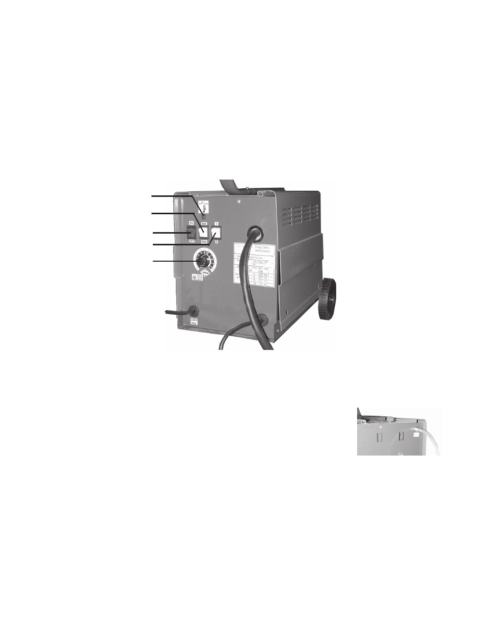
On / Off Switch
Min / Max Switch
1 / 2 Power Level Switch
Overload-shutdown
Indicator Lamp
Wire Feed Speed Control
Line Cord
Ground Cable with Clamp (15)
Welding Torch Cable (16)