Habey BIS-6590 User Manual
Page 25
3.1.5 Power Interface (DC_JACK)
3.2 Jumper Settings
3.2.1 CMOS Clear/Hold Jumper Setting (JCC)
3.1.6 USB Ports (USB12, USB34, USB56)
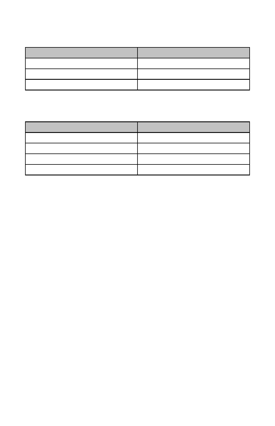
DC_JACK:
Pin
Signal Name
1
+12V
2
GND
3
NC
USB12, USB 34, USB56:
Pin
Signal Name
1
+5V
2
USB DATA-
3
USB DATA+
4
GND
Please refer to following instructions to do jumper settings before install-
ing the motherboard. Remark: How to identify the PIN1 of all jumpers and
interfaces: Please observe the word mark on the side of the plug socket,
which will be a “1” or bold line or triangular symbol; And please look at
the back of PCB, each with a square shape will be the PIN 1; and all the
jumpers’ PIN1 have a white arrow on the side.
CMOS is powered by the onboard button cell. Clear CMOS will lead to
permanent elimination of previous system settings and back to the original
system setting (factory default).
Steps:
(1) Turn off the computer and disconnect power supply.
(2) Use Jumper Cap JCC Pin1-2 short for 5~6 sec. Then restore the de-
fault setting with Pin2-3 connected.
(3) Turn on the computer, then press “DEL” key to enter BIOS setting and
reload optimal defaults.
(4) Save and Exit.
20