Principles of operation, Circuit, Archived 6/1/10 – ETS-Lindgren 94456 Current Probe (Archived) User Manual
Page 6
Principles of Operation
MODEL 94456 CURRENT PROBES
2
© EMC TEST SYSTEMS, L.P. – MARCH 2002
REV B – PN 399265
PRINCIPLES OF OPERATION
The RF Current Probe, Model 94456 is an inserted-primary
type of radio frequency current transformer. When the
probe is clamped over the conductor or cable in which
current is to be measured, the conductor forms the primary
winding. The clamp-on feature of this probe enables easy
placement around any conductor or cable.
CIRCUIT
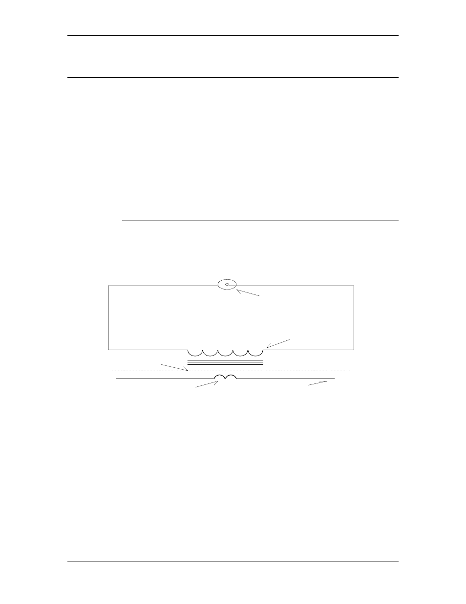
The circuit is that of a radio frequency transformer as
illustrated below:
O u t p u t t o C o a x i a l C a b l e
5 0 O h m s I m p e d a n c e
S e c o n d a r y W i n d i n g
E l e c t r o s t a t i c
S h i e l d ( C a s e )
N o i s e C u r r e n t s
P r i m a r y ( T e s t S a m p l e L e a d )
Figure 1. Basic RF Transformer
Since the current probe is intended for “clamp on”
operation, the primary shown in Figure 1 is actually the
electrical conductor in which interference currents are to be
measured. This primary is considered as one turn since it is
assumed that the noise currents flow through the conductor
and return to the source via a “ground” conductor such as a
frame, common ground plane, or earth. On some current
probe models the secondary output terminals are resistively
Archived 6/1/10