ETS-Lindgren 3121D Dipole User Manual
Page 19
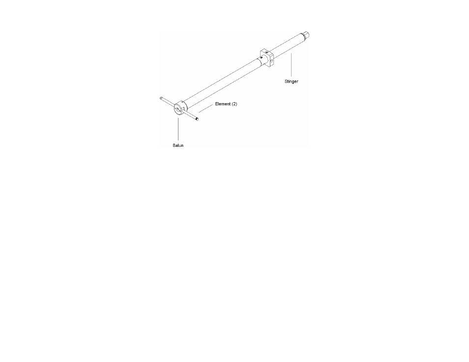
Assembly Instructions
|
19
3121D DB-4
3.
Balun DB-1 requires the use of two extension rods on each leg of the
dipole. Attach the longest collapsible elements to the extension rods.
4.
Place the balun in the tripod clamp and extend the elements to proper
length as specified by the Element Length Frequency Chart on
page 14. See Mounting Instructions on page 21 for the steps to mount
the Model 3121D Adjustable Dipole Antenna System.
This method is used for baluns DB-1, DB-2, and DB-3. At frequencies
above 400 MHz, balun DB-4 should be used and the dipole length
adjusted as specified on the engraved plastic ruler.
Typical Data
on page 27 provides the factors in dB which should be added to the
receiver or spectrum analyzer reading in (dBuV) to calculate the field strength in
dBuV/Meter.