Wiring – Code 3 Remote Compact Siren User Manual
Page 4
The siren chassis should be mounted with user provided hardware appropriate for the chosen mounting
location.
NOTE: Wiring will be performed in subsequent steps that will require access to the interior of the
unit. Plan the installation accordingly.
4
Wiring
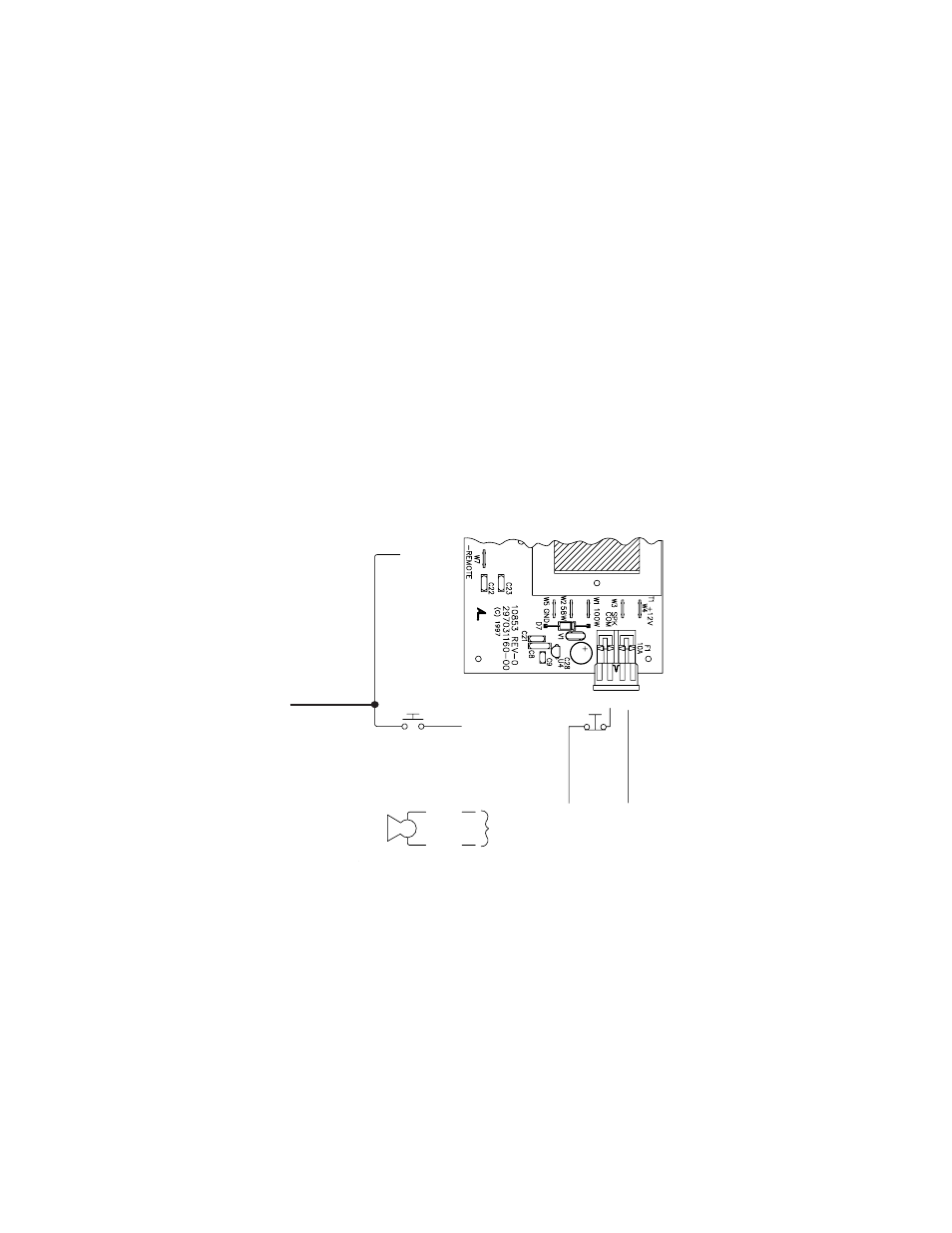
The 3920 siren provides six 1/4" Quickslide connections on the printed circuit board for power, control and
speaker connections. Each printed circuit board connection is clearly marked for easy identification. Wiring
connections are shown in Figure 2.
Provide a "service loop" of six to eight inches of each wire coming to the siren to allow easy removal and
access to the siren.
14AWG BLK
GROUND
(EARTH)
14AWG RED
IGNITION
SWITCHED
+12VDC
W7
W4 W5
10A FUSE
FIGURE 2
14AWG
14AWG
100W
SIREN
SPEAKER
100W (3920) - TERMINALS W1 / W3
58W (3925) - TERMINALS W2 / W3
GROUND
(EARTH)
OFF SWITCH
SCROLL SWITCH*
VEHICLE HORN
SWITCH*