Warning, Caution - ratchet head – CDI Torque PRE-SET TORQUE WRENCH User Manual
Page 2
sAFETY MEssAGEs
WARNING
Read operation manual completely
before using torque instrument and
store for future reference.
Wear safety goggles-both user and
bystanders
• An out of calibration torque wrench
can cause part or tool breakage
• Periodic re-calibration is necessary to
maintain accuracy
• Do not exceed rated torque as
overtorquing can cause wrench or part
failure
• Do not use torque instrument to break
fasteners loose
• Do not use cheater extension on the
handle to apply torque
• Broken or slipping tools can cause
injury.
CAUTION
- RATCHET HEAD
Ratchet mechanism may slip or break
if dirty, mismatched or worn parts are
used, or direction lever is not fully
engaged. Ratchets that slip or break
can cause injury.
MAINTENANCE / sERvICE
1. The torque wrench’s internal mechanism is
permanently lubricated during assembly.
Do not
attempt to lubricate the internal mechanism.
2. Clean torque wrench by wiping.
Do not immerse.
3. Store torque wrench in protective tube at its lowest
torque setting.
Do not force handle below lowest
setting.
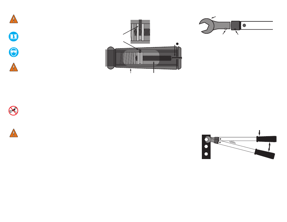
ADJUsTMENTs OF
TORQUE sETTINGs
1. To set the torque values, loosen locking set screw
(A) with a 3/32” hex wrench.
2. Insert interchangeable plain drive head (D) (consult
factory for model number) into receptacle (F)
until the locking pin (E) is fully engaged with the
corresponding receptacle hole. (See Figure I)
3. Place a T- handle hex wrench through adjusting hex
opening (C) at rear of handle grip until engaging the
adjusting screw (B).
4. Place the wrench on a torque tester. Turn adjusting
screw (B) with the T- handle hex wrench clockwise
to increase torque and counter-clockwise to
decrease torque.
5. To set torque, apply a slow steady force on the
pre-set wrench. Turn adjusting screw (B) until the
desired torque setting is displayed on the torque
tester.
6. Tighten the locking set screw to 10 in, lbs. (A). To
ensure that wrench setting is repeatable, cycle
three more times. If the readings are not as desired,
repeat steps 1-5.
NOTE:
• Some interchangeable heads used in pre-set torque
wrenches have lengths that vary.
• It is recommended that the pre-set torque wrenches
are to be calibrated with the interchangeable head
that is to be used to assure the greatest accuracy in
calibration.
• Hex wrenches used to adjust torque settings will
vary in length.
To verify calibration or to torque a fastener, keep hand
centered on the handle grip. Apply a slow force until
a click/impulse is heard or felt. Stop and allow the
wrench to reset.
Figure I
sETTING TORQUE
LOCKING SET
SCREW (A)
HANDLE
GRIP
ADJUSTING
SCREW (B)
ADJUSTING HEX
OPENING (C)
INTERCHANGEABLE
HEAD (D)
LOCKING
PIN (E)
RECEPTACLE (F)
APPLY FORCE
RELEASE
FORCE TO RESET
CLICK