Using sd extender board, Test points, Over-current protection – Bplus SDEX User Manual
Page 3: Power indicator
SD Extender Board 1.0_User’s Manual
Page 2
FAE2009SDEX_01 ©2009
Bplus Technology
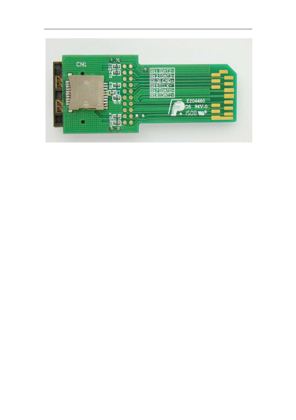
Figure-2 SD Extender Board 1.0(back)
2.1
Using SD Extender Board
SD Extender Board1.0 is fairly easy to use. The SD Extender is inserted into
the host socket with the connector pattern facing down.
Caution: You should insert, remove the extender and SD card carefully. The SD
connector’s pins may be broken or bent if improper force is used. Both extender and card
should be inserted straight. Care of extender will ensure your long years of trouble free
service.
2.2
Test points
All 13 pins of the interface are available to probe through clearly marked
resister.
Note: See the reference table printed on PCB.
2.3
Over-current protection
With a PTC fuse, the extender has the over-current protection function. The
function is available when headerJP1 keeps ‘OPEN’ status.
2.4
Power Indicator
The LED may indicate the status of the host socket’s VDD. When the header
JP2 keeps ‘SHORT’ status, the PWR LED is on.
Note: The LED does not provide the accurate measurement of VDD. Use a voltmeter to
determine the actual operating voltage.