Support bars installation 2a, 2e 2d – Alumax L-313 User Manual
Page 12
INSTRUCTION MANUAL
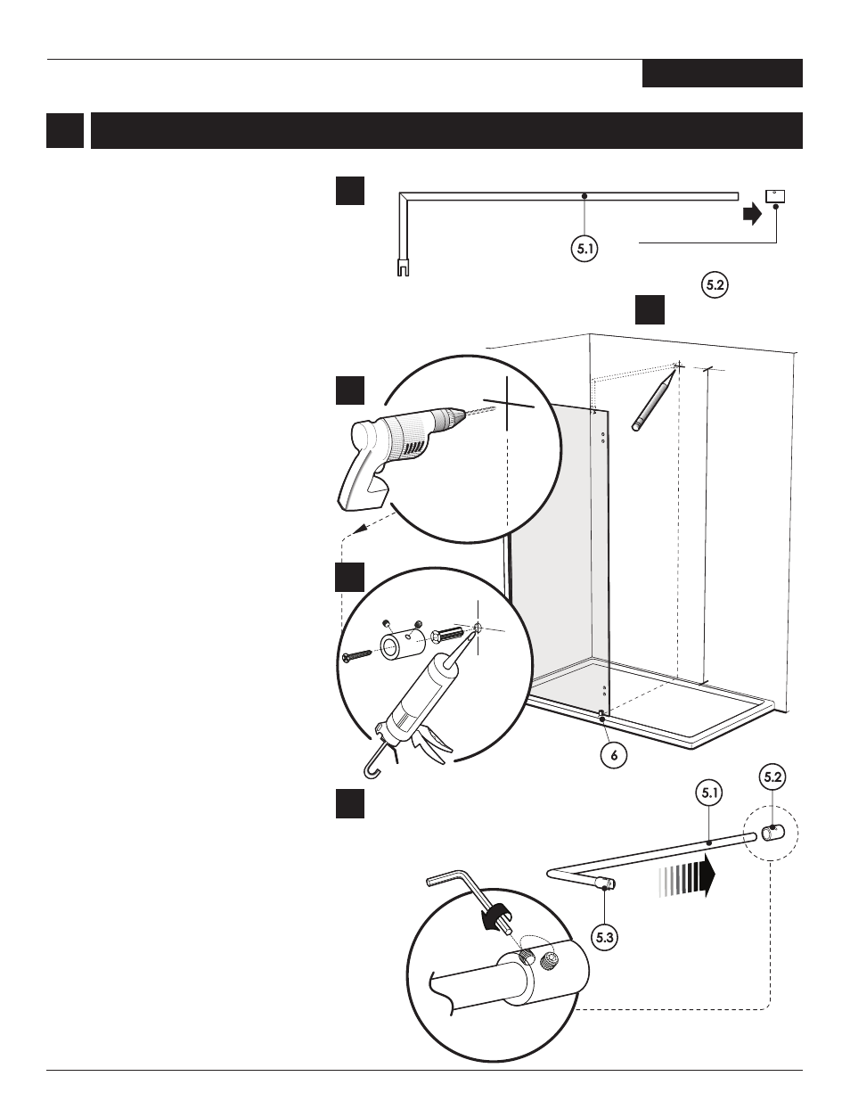
SUPPORT BARS INSTALLATION
2a
2
2a. Take apart the end component of the
support bar with the provided Allen
Key.
2e Insert the bar (5.1)into de wall end
component (5.2). Bars positioning must
be in an horizontal plane in order to
allow for glass panel installation. Tight
the bar with set screw.
2e
2d
WALL END COMPONENT
5.1
6
9
5.2
MIN 82” | MAX
. 82 1/4”
DIST
W
F
O
RE
T
NE
C
OT
DL
O
HS
E
R
HT
F
O
P
OT
M
O
RF
E
C
NA
T
NE
N
OP
M
O
C
D
NE
LL
A
2b. Transfer the position of the bottom clips
(6) to the back wall. At 82” from the
threshold mark the position (center of
the cylinder 5.2) for the support bar
end component mounting.
Drill the back wall using a 1/4”drill bit.
Apply silicone in the holes and insert
the wall plugs. Proceed to fasten the
wall end components to the wall.
2c
2c.
2d.
5.1
5.2
5.3
2b
203X, 313X, 313TBX