Front, Fuse – Carver ZR500 User Manual
Page 6
READY
PROTECT
THERMAL
CLIP
- 6dB
0dB
SIGNAL
HIGH
PASS
HIGH
PASS
CLIP
LIMITER
40Hz
80Hz
0dB
40Hz
80Hz
0dB
1 2 3
4
6
7 8
10 11 12
5
9
15
16
19
18
has been removed
T
6A-125VAC
CH 2
BRIDGED
MONO
AC Mains 120V (50-60Hz)
See user’s manual
CH2+
CH2-
CH1+
CH1-
MONO+
MONO-
Pin 1+
Pin 1-
Pin 2+
Pin 2-
Pin 1+
Pin 1-
Pin 1+ or 2+
Pin 1- or 2-
CH2
MONO
CH1
SEQUENCE
FUSE
17
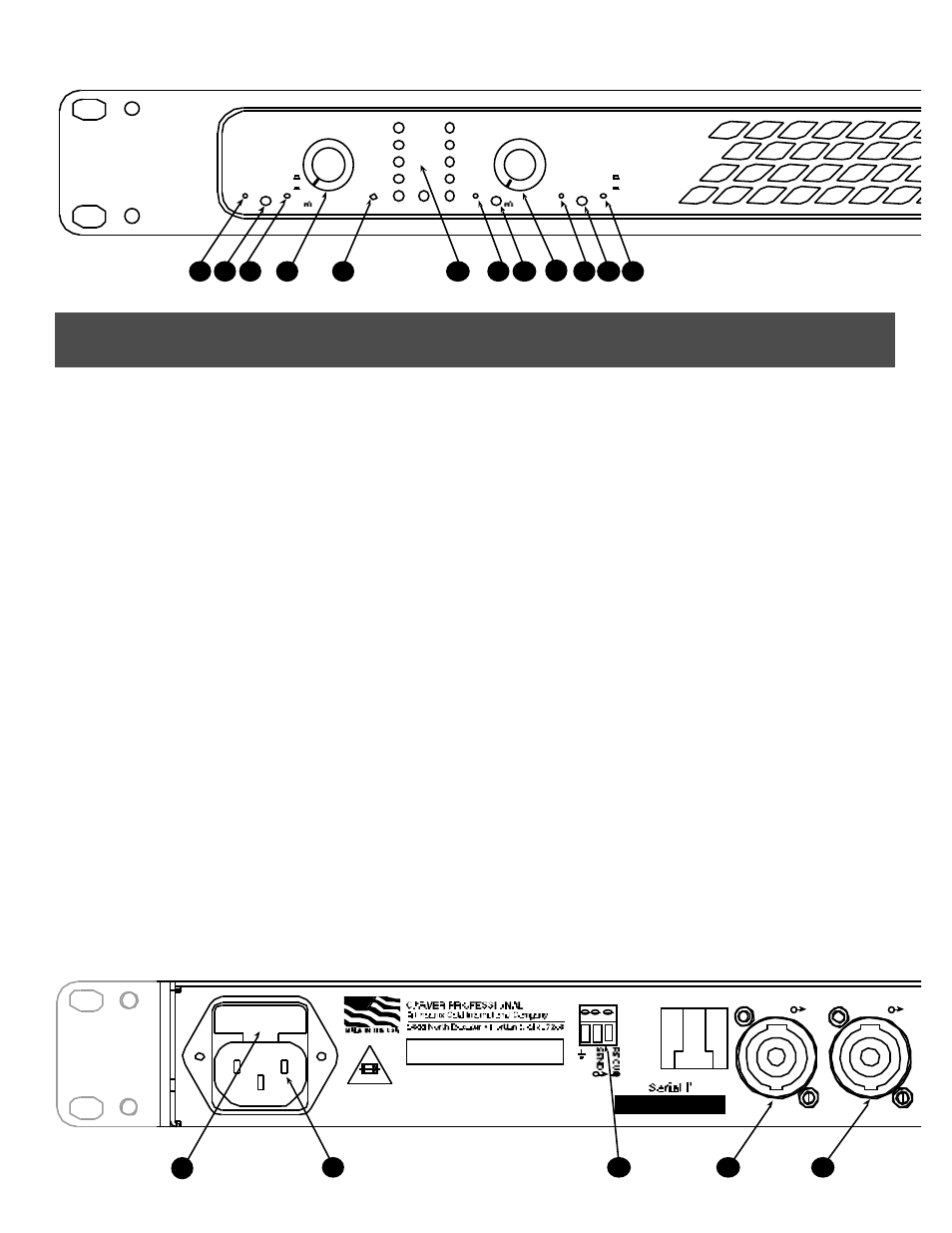
1 & 10 – HIGH PASS FILTER SWITCHES
Separate switches on each channel to enable highpass filters.
Highpass filters cut off the lowest frequencies to eliminate
rumble and prevent excess speaker excursion. The filter is
enabled when the switch is pushed in.
2 & 11 – HIGH PASS FILTER STATUS LEDS
Separate indicators on each channel illustrate the highpass filter
status. The LED is dark when the filter is not engaged. A Red
color indicates the cutoff is set at 40Hz, green indicates the
cutoff is set at 80Hz.
3 & 12 – HIGH PASS FILTER CUTOFF
FREQUENCY SELECTOR SWITCHES
Separate switches for each channel select the highpass filter
cutoff frequency. When the switches are out, the cutoff is set at
40Hz. When the switches are in, the cutoff is set at 80Hz.
5 – LEVEL CONTROL DEFEAT
When the switch is in, the level controls are set to 0dB
attenuation no matter what the position of the knobs.
4 & 9 – LEVEL CONTROLS
Sets the amount of signal attenuation, down to a maximum of
–100dB.
6 – SIGNAL LEVEL AND DIAGNOSTIC LEDS
An array of indicators that show the operational status of the
amplifier and the signal level.
PROTECT: Whenever a very low impedance (short circuit) is detected on
either of the outputs, or an over voltage, under voltage or over current
situation is detected the amplifier will protect itself and connected loads by
immediately ceasing to drive the output stage.
READY: The amplifier is operational.
THERMAL: Whenever the output section and/or the power transformer
exceeds preset thermal limits, the amp is disabled and will resume once it
has cooled.
SIGNAL: Indicates a signal is detected at the input.
– 6dB: Indicates the output has reached a level 6dB below rated power.
0dB: Indicates the amplifier is producing full output (or slightly below,
depending on load impedance).
CLIP: Indicates the output signal is reaching approximately 1% distortion.
7 – CLIP LIMITER SWITCH
When the switch is in the clip limiter is enabled.
8 – CLIP LIMITER STATUS LED
Indicates when the clip limiter is enabled.
13 – STANDBY LED
Indicates that the amp is in Standby mode. When in Standby
mode, the amplifier is turned “OFF”, but the AC Mains are
connected and the amplifier waits for a DC voltage at the
Sequence connector on the rear of the amp. Once a DC voltage
is applied to the Sequence connector, the amp turns “ON” and
begins its start-up diagnostics and upon completion is ready for
use.
14 – POWER SWITCH
A three-position switch used to select the power operation
mode. In the center position, power is off. In the up position,
power is on. In the down position, amp is set to standby mode.
FRONT
6