Step 26: (see figure 25 or 26), On tractors without foot rest brackets, Step 28: (see figure 28) – Craftsman 486.24837 User Manual
Page 15
Attention! The text in this document has been recognized automatically. To view the original document, you can use the "Original mode".
INSTALLING HANGER BRACKETS
For better clearance, lower the tractor's suspension arms
using the attachment lift lever.
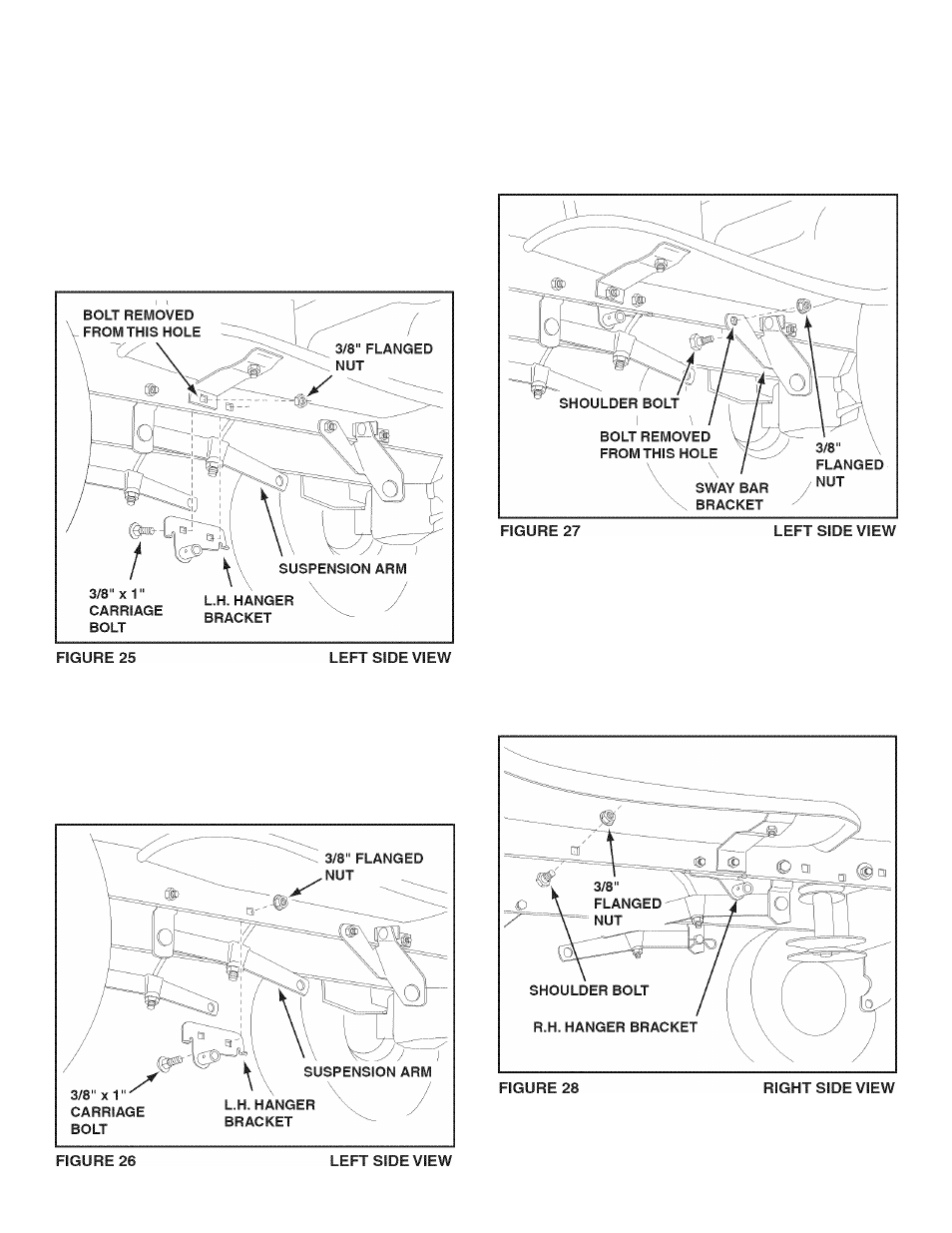
STEP 26: (SEE FIGURE 25 or 26)
On Tractors With Foot Rest Brackets
•
Remove the bolt and nut that fasten the L.H. and R.H.
foot rest brackets to the frame.
•
Attach the L.H. Hanger Bracket (marked "L") to the
Inside of the tractor frame using two 3/8" x 1" carriage
bolts and 3/8" flanged nuts. Bolt heads go on Inside of
tractor frame. Repeat for the R.H. side.
On Tractors Without Foot Rest Brackets
• Find the empty hole beneath the foot rest. Attach the
L.H. Hanger Bracket (marked "L") to the inside of
the frame using a 3/8" x 1" carriage bolt and a 3/8"
flanged nut. Bolt head goes on inside of tractor frame.
Repeat for the R.H. side.
INSTALLING SHOULDER BOLTS
STEP 27: (SEE FIGURE 27)
• Remove the bolt, washer and nut which fasten the
sway bar bracket to the L.H. side of the tractor frame.
Replace with a shoulder bolt and a 3/8" flanged nut.
Bolt goes on inside of frame.
STEP 28: (SEE FIGURE 28)
• Assemble a shoulder bolt and 3/8" flanged nut to the
R.H. side of the tractor frame, using the first empty
hole to the rear of the R.H. hanger bracket. Bolt goes
on inside of frame.
15