Connect shift rod (see fig. 6), Remove tiller from crate, Insert cable clip (see fig. 7) – Craftsman 917.295550 User Manual
Page 8: Handle height, Assembly
Attention! The text in this document has been recognized automatically. To view the original document, you can use the "Original mode".
ASSEMBLY
CONNECT SHIFT ROD (See Fig. 6)
•
Insert end of shift rod farthest from bend into hole of
shift lever indicator.
•
Insert hairpin clip through hole of shift rod to secure.
•
Insert other end of shift rod Into hole in shift lever.
•
Insert second hairpin clip through hole of shift rod.
ATTACH THIS END
TO SHIFT LEVER
INDICATOR
ATTACH THIS
END TO SHIFT
LEVER
SHIFT ROD
SHIFT LEVER
D
■ HAIRPIN CUP
SHIFT ROD
REMOVE TILLER FROM CRATE
" Make sure shift lever indicator is in “N” (neutral) posi
tion (See Fig. 6)
•
Tilt tiller forward by lifting handle. Separate cardboard
cover from leveling shield,
•
Rotate tiller handle to the right and pull tiller out of
carton.
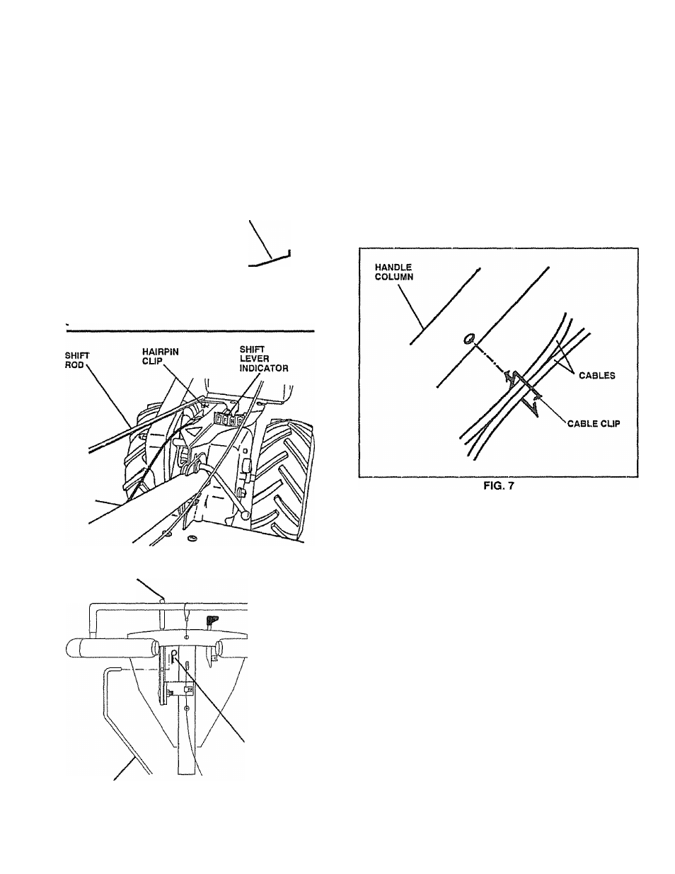
INSERT CABLE CLIP (See Fig. 7)
•
Insert plastic cable clip into hole on the back of handle
column. Push cables into clip.
TfD!:: D D C C C i i D i r
iMwlw^ |V I II
i
W
m
V*'it C
m
C) V
i
/1« Cl
The tires on your unit were overinflated at the factory for
shipping purposes- Correct and equal tire pressure is
important for best tilling performance.
•
Reduce tire pressure to 20 PS!.
HANDLE HEIGHT
•
Handle I
(See “TO-
and Adjustments section of this manual).
FIG. 6
8