Assembly instructions, Items you will need to assemble your compressor, Installing handle – Craftsman 919.17673 User Manual
Page 7
Attention! The text in this document has been recognized automatically. To view the original document, you can use the "Original mode".
Pressure Switch: The pressure switch automaticaily
starts the motor when the air tank pressure drops below
the factory set “cut-in" pressure. It stops the motor when
the air tank pressure reaches the factory set “cut-out"
pressure.
Regulator: The air pressure coming from the air tank is
controlled by the regulator knob. Turn the knob
clockwise to increase pressure and counterclockwise to
decrease pressure. To avoid minor readjustment after
making a change in pressure setting, always approach
the desired pressure from a lower pressure. When
reducing from a higher to a lower setting, first reduce to
some pressure less than that desired, then bring up to
the desired pressure. Depending on the air requirements
of each particular accessory, the outlet regulated air
pressure might have to be adjusted while you are
operating the accessory.
Tank Pressure Gauge: The tank pressure gauge indi
cates the reserve air pressure in the tank.
Outlet Pressure Gauge: The outlet pressure gauge
indicates the air pressure available at the outlet side of
the reguiator. This pressure is controlled by the regulator
and is always less or equal to the tank pressure. See
“Operating Procedures.”
ASSEMBLY INSTRUCTIONS
Items You Will Need To Assemble Your
Compressor
• 16 oz. compressor oil. Sears 9-16426 or SAE 20-20W
SF motor oil
• pipe thread sealant
• an adjustable wrench for attaching the pressure
regulator
• a 9/16" socket or open-end wrench for attaching the
wheels and hose adapter
• a 7/16" open-end wrench for attaching the air pressure
gauges
• a 3/16" hex key for installing the plug in the regulator
Installing Handle
W A R N I N G
]
THE WHEELS HAi^lDLE DO NOT PRO
VIDE ADEQUATE CLEARAriCE. STAS?LITY
C.SR SOPPORT FOR PyUJMG THE Uf--J!T UP
Am DO\m
smiHS
or
-
step
-
s
.
the
unit
MUST BE LiPTED OR PUSHED UP
A fiAMP.
DO MOT LiFT THE Ul^iT BY THE MANIFOLD
A.SSEfyiBLy. THE UM!T
CAM
BE DAMAGED,
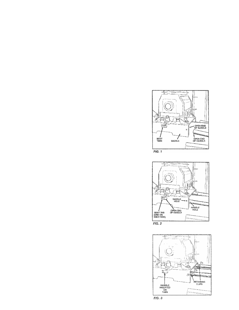
1 Insert the open end of the handle under the saddle (Fig.
1). Before attaching handle, you may have to pull the
open ends of the handle apart so they fit tightly against
the side of the saddle. Looking in from the open end of
the saddle, position the handle towards the two bent
tabs, on the inside walls of the saddle.
Slowly
push the
open ends of the handle onto both tabs at the same
time (Fig. 2). Continue pushing the handle into the sad
dle until the holes on the side of the saddle and handle
are in line.
2. Guide the straight end of each retaining clip through the
saddle hole and both handle holes (Fig. 3).
3. Rotate each retaining clip clockwise and press down
until it snaps into place over the puli handle (Fig. 4).
4. If the handle has excessive movement, it is improperly
installed. Check the following;
A. Are both tabs inside the handle (Step #1)?
B. Does each dip pass through both the saddle and
handle (Step #2)?