Craftsman 917.273800 User Manual
Page 26
Attention! The text in this document has been recognized automatically. To view the original document, you can use the "Original mode".
5. Remove belt from center span keeper
and pull belt away from tractor.
BELT INSTALLATION -
1. Carefully work new belt down around
transmission cooling fan and onto the
input pulley.
2. Slide belt into the center span keeper.
3. Pull belt toward front of tractor and roll
around the top groove of engine pulley.
4. Install belt through stationary idler and
clutching idler.
5. Make sure belt is in all pulley grooves
and inside all belt guides and keepers.
6. Install mower (See “TO INSTALL
MOWER” in this section of manual).
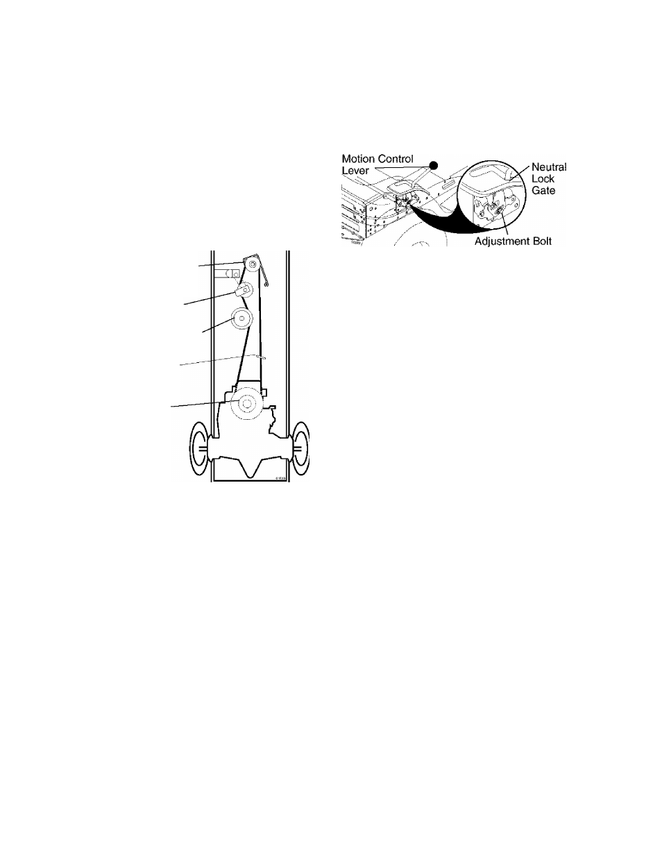
Engine Pulley
Clutching Idler
Stationary Idler
Center Span
Keeper
Transmission
Input Pulley
TRANSAXLE MOTION CONTROL LE
VER NEUTRAL ADJUSTMENT
The motion control lever has been preset
at the factory and adjustment should not
be necessary.
1. Loosen adjustment bolt in front of the
right rear wheel, and lightly tighten.
2. Start engine and move motion con
trol lever until tractor does not move
forward or backward.
3. Hold motion control lever in that posi
tion and turn engine off.
4. While holding motion control lever in
place, loosen the adjustment bolt.
5. Move motion control lever to the neu
tral (N) (lock gate) position.
6. Tighten adjustment bolt securely.
NOTE:
If additional clearance is needed
to get to adjustment bolt, move mower
deck height to the lowest position.
After above adjustment is made, if the
tractor still creeps forward or backward
while motion control lever is in neutral
position, follow these steps;
1. Loosen the adjustment bolt.
2. Move the motion control lever 1/4 to
1/2 inch in the direction it is trying to
creep.
3. Tighten adjustment bolt securely.
4. Start engine and test.
5. If tractor still creeps, repeat above
steps until satisfied.
TRANSMISSION REMOVAL/
REPLACEMENT
Should your transmission require removal
for service or replacement, it should be
purged after reinstallation and before op
erating the tractor. See “PURGE TRANS
MISSION” in the Operation section of this
manual.
TO ADJUST STEERING WHEEL ALIGN
MENT
if steering wheel crossbars are not
horizontal (left to right) when wheels are
positioned straight forward, remove steer
ing wheei and reassemble with crossbars
horizontal. Tighten securely.
FRONT WHEEL TOE-IN/CAMBER
The front wheel toe-in and camber are not
adjustable on your tractor. If damage has
occurred to affect the front wheel toe-in or
camber, contact a Sears or other qualified
service center.
TO REMOVE WHEEL FOR REPAIRS
1. Block up axle securely.
2. Remove axle cover, retaining ring and
washers to allow wheel removal (rear
wheels have a square key - Do not
lose).
3. Repair tire and reassemble.
NOTE:
On rear wheels only: align
grooves in rear wheel hub and axle. Insert
square key.
4. Replace washers and snap retaining
ring securely in axle groove.
5. Replace axle cover.
NOTE:
To seal tire punctures and prevent
flat tires due to slow leaks, purchase and
use tire sealant from Sears. Tire sealant
also prevents tire dry rot and corrosion.
26