Installing bits, Removing bits, Using depth gage rod – Craftsman 315.271270 User Manual
Page 10: Assembly
Attention! The text in this document has been recognized automatically. To view the original document, you can use the "Original mode".
ASSEMBLY
INSTALLING BITS
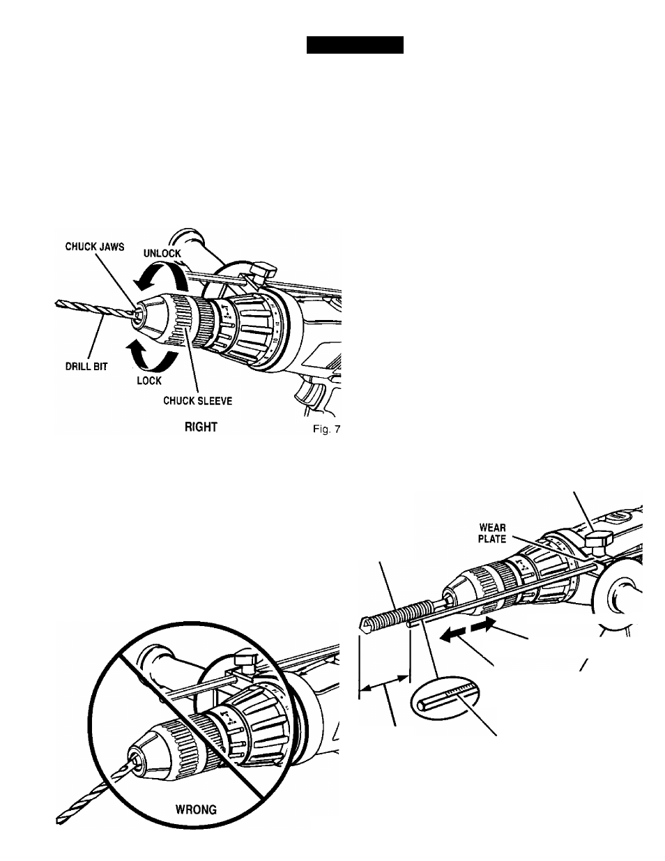
See Figure 7.
■
Lock the switch trigger by placing the direction of
rotation selector in center position. See Figure 13.
■
Open or close chuck jaws to a point where the open
ing is slightly larger than the bit size you intend to use.
Aiso, raise the front of your drill slightly to keep the bit
from falling out of the chuck jaws.
■
Insert drill bit into chuck the full length of the jaws as
shown in Figure 7.
Tighten the chuck jaws on drill bit. To tighten, grasp
and hold the drill with one hand, while rotating the
chuck sleeve with your other hand.
Note:
Rotate the chuck sleeve in the direction of the
arrow marked
LOCK
to tighten chuck jaws.
Do not
use a wrench to tighten or loosen the chuck
jaws.
^ WARNING:
Do not insert driil bit into chuck jaws
and tighten as shown in Figure 8. This could cause
drill bit to be thrown from drill resulting in possible
serious personal injury or damage to the chuck.
REMOVING BITS
See Figure 7.
■
Lock the switch trigger by placing the direction of
rotation selector in center position. See Figure 13.
■
Loosen the chuck jaws from drill bit.
■
To loosen, grasp and hold the drill with one hand,
while rotating chuck sleeve with your other hand.
Note:
Rotate chuck sleeve in the direction of the arrow
marked
UNLOCK
to loosen the chuck jaws.
■
Do not
use a wrench to tighten or loosen the chuck
jaws.
■
Remove drill bit from chuck jaws.
USING DEPTH GAGE ROD
See Figure 9.
A depth gage rod has been packed with your hammer drill
to assist you in controlling the depth of drilled holes.
■
Loosen wing screw on auxiliary handle.
■
Orient depth gage rod so that markings on depth gage
rod face markings on wear plate. See Figure 4. Insert
depth gage rod through hole on auxiliary handle.
■
Adjust depth gage rod so that the drill bit extends
beyond the end of the rod to the required drilling
depth.
■
Tighten wing screw securely. This secures depth
gage rod at desired depth of cut. It also secures
auxiliary handle.
WING
SCREW
DRILL BIT
DRILLING
DEPTH
TO
INCREASE
DRILLING
DEPTH
■ TO
DECREASE
DRILLING
AUXILIARY
DEPTH
HANDLE
MARKINGS ON
DEPTH GAGE ROD
Fig. 9
Fig. 8
When drilling holes with the depth gage rod installed, the
desired hole depth has been reached when the end of the
rod comes in contact with the surface of the material
being drilled.
10