Craftsman 919.679501 User Manual
Page 19
Attention! The text in this document has been recognized automatically. To view the original document, you can use the "Original mode".
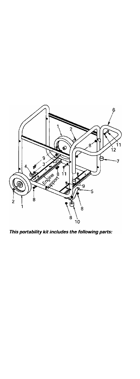
Repeat the above steps for the opposite side.
Insert the threaded stud of rubber foot (10)
through the middle hole of the foot bracket (5).
Secure with lock nut (8) and tighten.
Locate the support under the electrical outlet end
of the generator. Position foot bracket (5), with
rubber foot installed, under the support and align
the holes in the foot bracket (5) with the slots in
the support. Place one cap screw (9) through each
slot in the support and the holes in the foot
bracket. Secure with the lock nuts (8) and tighten.
Once completed, the wheel kit is ready for use.
Key
No.
Description
PART NO.
1
Wheel (2 used)
AC-0014
2
Shoulder Bolt (2 used)
CAC-60
3
Lock Nut 3/8"-16 (2 used)
SSF-8111-ZN
4
Wheel Bracket (2 used)
GS-0561
5
Foot Bracket
GS-0562
6
Handle
GS-0564
7
Handle Cap (2 used)
GS-0565
8
Lock Nut 5/16"-18(9 used)
SSF-8150
9
Cap Screw 5/16"-18 x 3/4"
(6 used)
SS-12-CD
10
Isolator Foot
GS-0587
11
Cap Screw 5/16-18x1.75"
(2 used)
SSF-999-1
12
Washer (2 used)
SS-6506-CD
-ENG