Engine, Preparation – Craftsman 247.298760 User Manual
Page 9
Attention! The text in this document has been recognized automatically. To view the original document, you can use the "Original mode".
NOTE
Shift lever and control rod must be
readjusted whenever you change the
handle height.
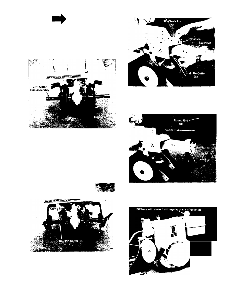
5. Tine Attachment
a. The outer tines have been reversed on the
tine shaft for shipping purposes. See
figure 14.
FIGURE 14.
Remove outer tines from the tine shaft and
reinstall with the tine hub facing inward as
illustrated in figure 15. Secure tines with clevis
pins (H) and hair pin cotters (C).
b. The inner tine assemblies have been
installed at the factory and in their correct
operating position and do not require
changing.
c. See tine adjustment for information on
changing width of tilling path, page 13.
I
FIGURE 15.
6. Tail Piece Attachment.
Slide the tail piece into the chassis and secure
with “U” clevis pin (A) and hair pin cotter (C). See
figure 16.
FIGURE 16.
7. Depth Stake Attachment.
Slide the depth stake into the tail piece (round end
up) and secure with clevis pin (H) and hair pin
cotter (C). See figure 17.
FIGURE 17.
ENGINE
PREPARATION
Oil Fill
Other Side of
Engine
FIGURE 18.