Assembly – Craftsman 486.24635 User Manual
Page 4
Attention! The text in this document has been recognized automatically. To view the original document, you can use the "Original mode".
ASSEMBLY
TOOLS REQUIRED FOR ASSEMBLY
(1) 3/4" Wrench or Adjustable Wrench
(1) 11/16“ Wrench or Adjustable Wrench
(1) 5/8“ Wrench or Adjustable Wrench
(2) 9/16" Wrenches or Adjustable Wrenches
(2) 1/2" Wrenches or Adjustable Wrenches
• Remove the hardware pack and all parts from the
carton. Be sure the carton is empty before discard
ing.
• Lay out all parts and hardware as shown on page 3.
FOR TRACTORS RESEMBUNG FIGURE 1:
• Remove the bolt from the hole on each side of the
tractor frame as shown in figure 1.
• Assemble the two shoulder bolts to the now empty
holes. Tighten. See figure 1.
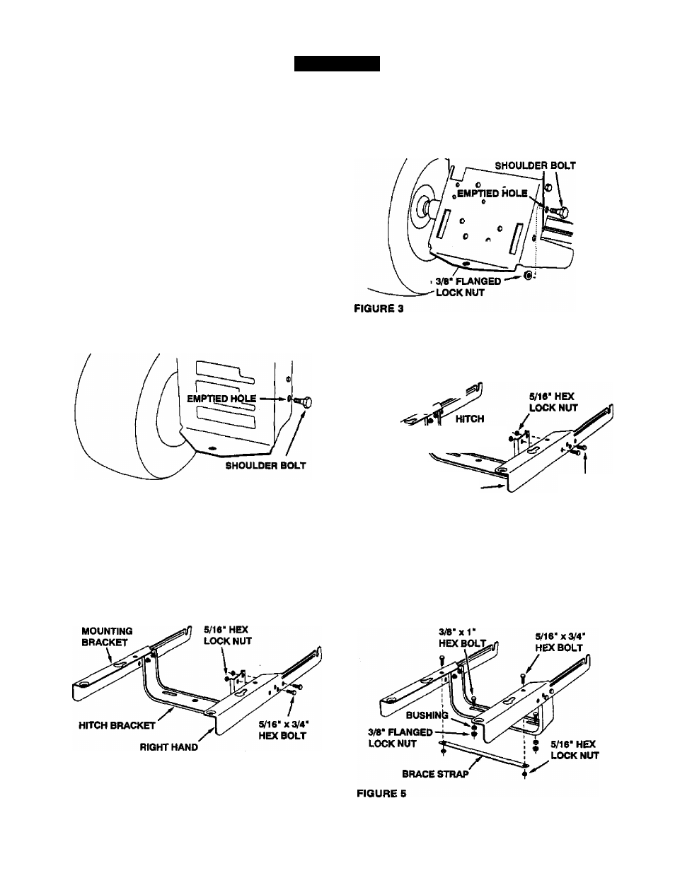
FOR TRACTORS RESEMBUNG FIGURE 2:
• Remove the bolt and nut from the hole on each side
of the tractor frame as shown in figure 3.
• Assemble two shoulder bolts and 3/8" flanged lock
nuts to the now empty holes. Tighten. See figure 3.
• Assemble the right and left mounting brackets to the
hitch bracket using four 5/16" x 3/4“ hex bolts emd
5/16" hex lock nuts. Do not tighten yet See figure 4.
LEFT HAND
MOUNTINQ BRACKET;
BRACKET
J
FIGURE 1
RIGHT HAND
MOUNTING BRACKET
FIGURE 4
5/16" x 3/4"
HEX BOLT
* Assemble the right hand and left hand mounting
brackets to the hitch bracket using four 5/16" x 3/4*
hex bolts and 5/16" hex lock nuts. Do not tighten
yet. See figure 2.
LEFT HAND
MOUNTINQ
BRACKET
FOR BOTH TYPES OF TRACTORS
• Assemble the brace strap to the mounting brackets
using two 5/16* X 3/4* hex bolts and 6/16* hex lock
nuts. Do not tighten yet. See figure 5.
• Assemble two 3/8" x 1" hex bolts, bushings and 3/8"
flanged lock nuts to the slots in the hitch bracket. Do
not tighten yet. See figure 5.
FIGURE 2