O o o o o o o o o, Pin assignment – Sony GVM-1311Q User Manual
Page 9
Attention! The text in this document has been recognized automatically. To view the original document, you can use the "Original mode".
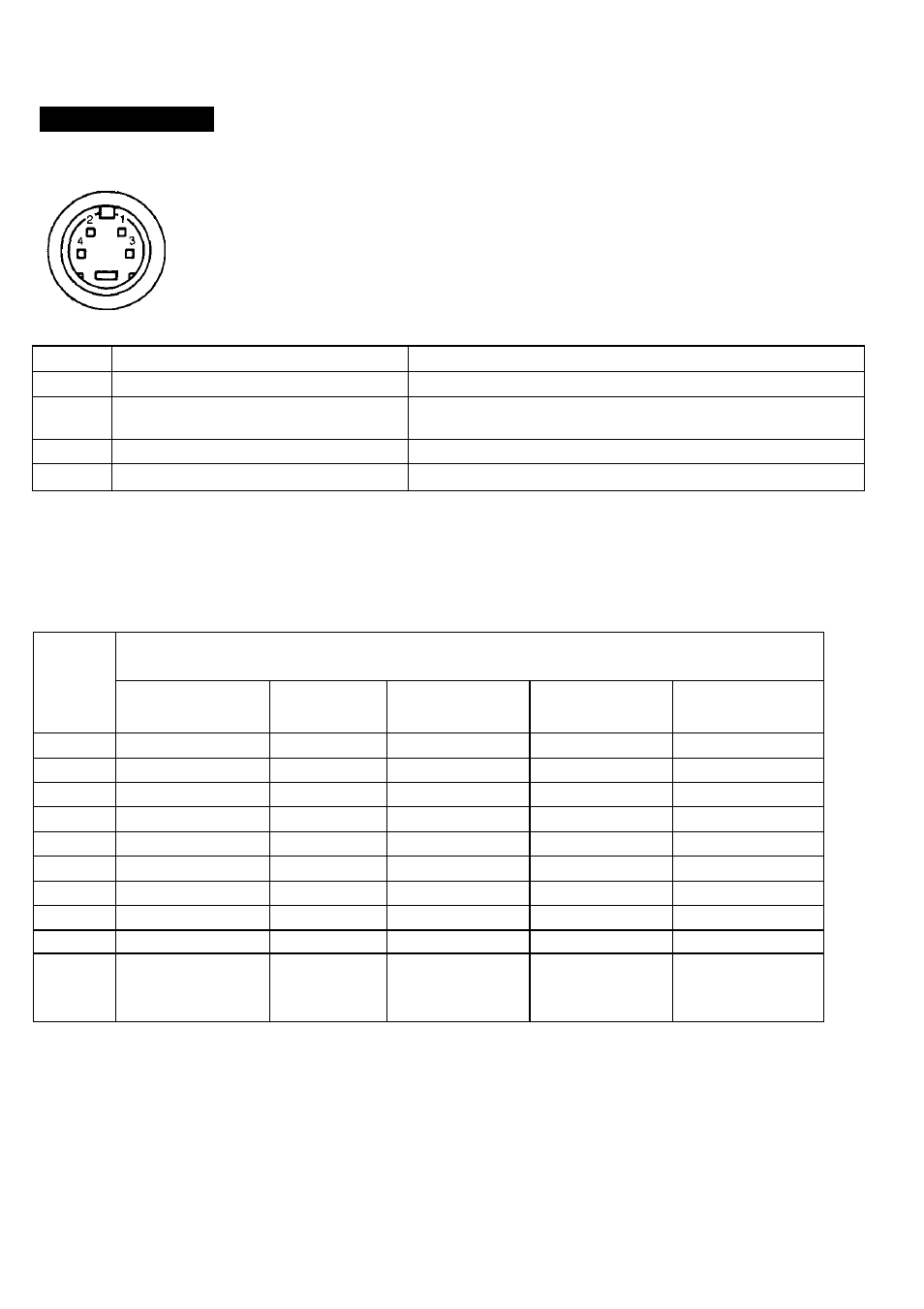
Pin assignment
Y/C (Y/C separate) IN connector (4-pin)
Pin No.
SlgMi
OM^^cin
1
Y-input
1 Vp-p, sync negative, 75 ohms
2
CHROMA sub-carrier-input
0.286 Vp-p (NTSC); 0.3 Vp-p (PAL), burst signal
Delay time between Y and C: within 0±100 nsec., 75 ohms
3
GND for Y-input
Ground
4
GND for CHROMA-input
Ground
RGB multi connector (9-pin, female)
5 4 3 2
o o o o o
o o o o
9
8
7
6
Pin
Signal
No.
Ant^
Digital
DIgittd
Digital
Digital
8-color
16-colòr
64-color
monochrome
1
GND
GND
GND
GND
GND
2
(NC)
(NC)
(NC)
r
(NC)
3
R
R
R
R
(NC)
4
G
G
G
G
(NC)
5
B
B
B
B
(NC)
6
(NC)
(NC)
1
9
1
7
(NC)
(NC)
(NC)
b
G
8
H/HV
H/HV
H/HV
H/HV
H/HV
9
V
V
V
V
V
Sync
TTL levei
TTL level
TTL level
TTL level
TTL level
level
(Positive or
(Positive or
(HiPositive
(H:Positive
(HiPositive
Negative)
Negative)
V'.Positive)
V-.Negative)
V-.Negative)
GND: Ground
(NC): No connection
H: Horizontal sync
HV: Composite sync
r: Secondary red
R: Red
G: Green
V: Vertical sync
i: Intensity
g: Secondary green
B: Blue
b: Secondary blue
9